Core peripherals PM0214
198/262 PM0214 Rev 9
; R1 = address and region number in one
; R2 = size and attributes in one
LDR R0, =MPU_RBAR ; 0xE000ED9C, MPU Region Base register
STR R1, [R0, #0x0] ; Region base address and
; region number combined with VALID (bit 4) set to 1
STR R2, [R0, #0x4] ; Region Attribute, Size and Enable
Use an STM instruction to optimize this:
; R1 = address and region number in one
; R2 = size and attributes in one
LDR R0,=MPU_RBAR ; 0xE000ED9C, MPU Region Base register
STM R0, {R1-R2} ; Region base address, region number and VALID bit,
; and Region Attribute, Size and Enable
Subregions
Regions of 256 bytes or more are divided into eight equal-sized subregions. Set the
corresponding bit in the SRD field of the RASR to disable a subregion, see Section 4.2.9:
MPU region attribute and size register (MPU_RASR) on page 204. The least significant bit
of SRD controls the first subregion, and the most significant bit controls the last subregion.
Disabling a subregion means another region overlapping the disabled range matches
instead. If no other enabled region overlaps the disabled subregion the MPU issues a fault.
Regions of 32, 64, and 128 bytes do not support subregions, With regions of these sizes,
you must set the SRD field to 0x00, otherwise the MPU behavior is Unpredictable.
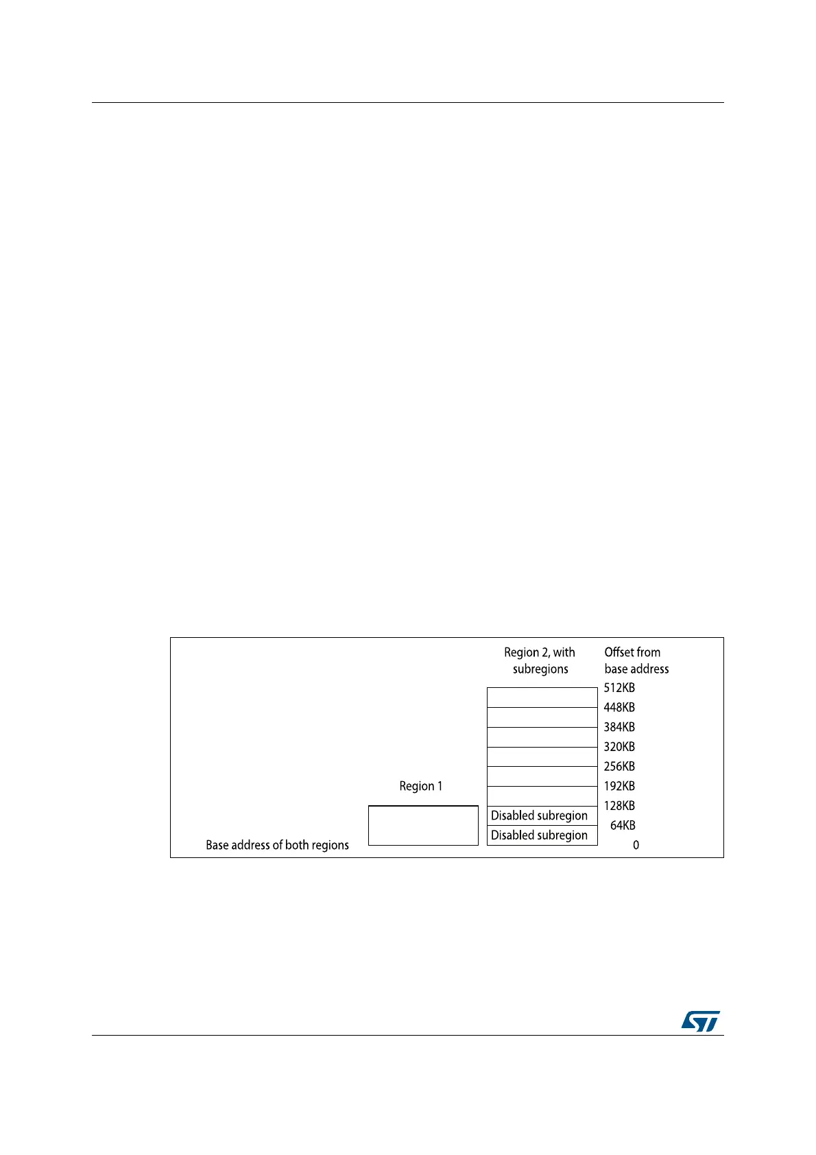
Example of SRD use:
Two regions with the same base address overlap. Region one is 128KB, and region two is
512KB. To ensure the attributes from region one apply to the first128KB region, set the SRD
field for region two to b00000011 to disable the first two subregions, as the figure shows.
Figure 18. Subregion example
 Loading...


