EasyManua.ls Logo

ST STM32H7 Series User Manual

ST STM32H7 Series
262 pages
To Next Page IconTo Next Page
To Previous Page IconTo Previous Page
Page #203 background imageLoading...
Page #203 background image
PM0214 Rev 9 203/262
PM0214 Core peripherals
261
4.2.8 MPU region base address register (MPU_RBAR)
Address offset: 0x0C
Reset value: 0x0000 0000
Required privilege: Privileged
The MPU_RBAR register defines the base address of the MPU region selected by the
MPU_RNR register, and can update the value of the MPU_RNR register.
Write to the MPU_RBAR register with the VALID bit set to 1 to change the current region
number and update the MPU_RNR register.
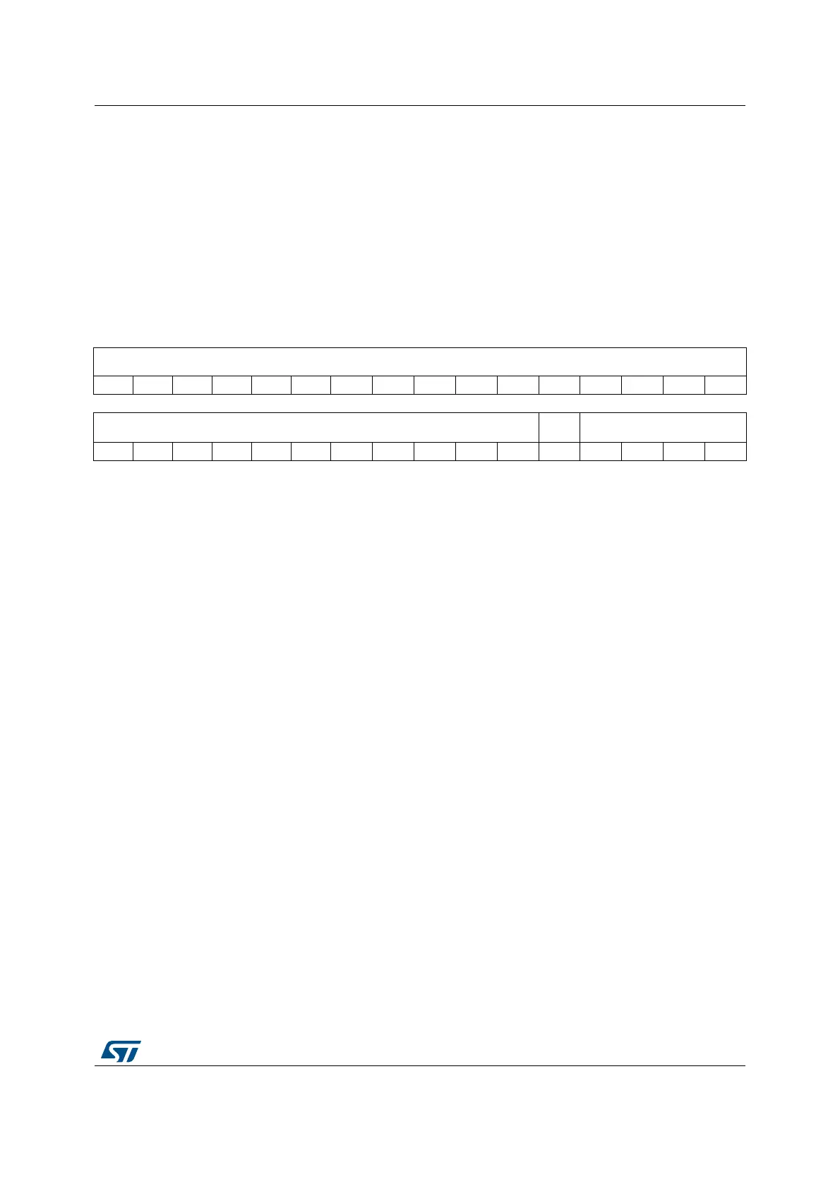
31 30 29 28 27 26 25 24 23 22 21 20 19 18 17 16
ADDR[31:N]...
1514131211109876543210
....ADDR[31:N] VALID REGION[3:0]
rw rw rw rw rw
Bits 31:N ADDR[31:N]: Region base address field
The value of N depends on the region size.
The region size, as specified by the SIZE field in the MPU_RASR, defines the value of N:
N = Log2(Region size in bytes),
If the region size is configured to 4 GB, in the MPU_RASR register, there is no valid ADDR
field. In this case, the region occupies the complete memory map, and the base address is
0x00000000.
The base address is aligned to the size of the region. For example, a 64 KB region must be
aligned on a multiple of 64 KB, for example, at 0x00010000 or 0x00020000.
Bits N-1:5 Reserved, forced by hardware to 0.
Bit 4 VALID: MPU region number valid
Write:
0: MPU_RNR register not changed, and the processor:
– Updates the base address for the region specified in the MPU_RNR
– Ignores the value of the REGION field
1: the processor:
– updates the value of the MPU_RNR to the value of the REGION field
– updates the base address for the region specified in the REGION field.
Read:
Always read as zero.
Bits 3:0 REGION[3:0]: MPU region field
For the behavior on writes, see the description of the VALID field.
On reads, returns the current region number, as specified by the MPU_RNR register.

Table of Contents

Other manuals for ST STM32H7 Series

Question and Answer IconNeed help?

Do you have a question about the ST STM32H7 Series and is the answer not in the manual?

ST STM32H7 Series Specifications

General IconGeneral
BrandST
ModelSTM32H7 Series
CategoryComputer Hardware
LanguageEnglish

Summary

About this document

Typographical Conventions

Defines formatting used in the document for clarity.

List of Abbreviations for Registers

Provides a list of abbreviations used in register descriptions for quick reference.

STM32 Cortex-M4 Processor Overview

Introduces the STM32 Cortex-M4 processor's architecture and key features.

The Cortex-M4 Processor

Programmer's Model

Describes registers, modes, and privilege levels for software execution.

Memory Model

Details the processor's memory map, access behavior, and bit-banding features.

Exception Model

Explains exception states, types, priorities, and handling mechanisms.

Fault Handling

Covers fault types, escalation, status registers, and lockup conditions.

Power Management

Describes mechanisms for entering and exiting low-power sleep modes.

The STM32 Cortex-M4 Instruction Set

Instruction Set Summary

Lists supported Cortex-M4 instructions and their organization.

Memory Access Instructions

Details instructions for loading and storing data from/to memory.

General Data Processing Instructions

Explains instructions for arithmetic, logical, and data manipulation.

Multiply and Divide Instructions

Describes instructions for multiplication and division operations.

Floating-Point Instructions

Details instructions for FPU operations, including VFPv4-SP extension.

Miscellaneous Instructions

Covers instructions like breakpoints, barriers, and supervisor calls.

Core Peripherals

About the STM32 Cortex-M4 Core Peripherals

Introduces the core peripherals accessible via the Private Peripheral Bus (PPB).

Memory Protection Unit (MPU)

Explains the MPU for memory region definition and access control.

Nested Vectored Interrupt Controller (NVIC)

Describes the NVIC for managing interrupts and exceptions with priority levels.

System Control Block (SCB)

Details registers for system control, configuration, and exception reporting.

SysTick Timer (STK)

Explains the 24-bit SysTick timer for system timing and RTOS ticks.

Floating Point Unit (FPU)

Describes the FPU for single-precision floating-point operations.

Revision History

Related product manuals