EasyManua.ls Logo

ST STM32H7 Series User Manual

ST STM32H7 Series
262 pages
To Next Page IconTo Next Page
To Previous Page IconTo Previous Page
Page #202 background imageLoading...
Page #202 background image
Core peripherals PM0214
202/262 PM0214 Rev 9
4.2.7 MPU region number register (MPU_RNR)
Address offset: 0x08
Reset value: 0x0000 0000
Required privilege: Privileged
The MPU_RNR register selects which memory region is referenced by the MPU_RBAR and
MPU_RASR registers.
Bits 31:3 Reserved, forced by hardware to 0.
Bit 2 PRIVDEFENA: Enable priviliged software access to default memory map.
0: If the MPU is enabled, disables use of the default memory map. Any memory access to a
location not covered by any enabled region causes a fault.
1: If the MPU is enabled, enables use of the default memory map as a background region for
privileged software accesses.
Note: When enabled, the background region acts as if it is region number -1. Any region that
is defined and enabled has priority over this default map.
If the MPU is disabled, the processor ignores this bit.
Bit 1 HFNMIENA: Enables the operation of MPU during hard fault, NMI, and FAULTMASK handlers.
When the MPU is enabled:
0: MPU is disabled during hard fault, NMI, and FAULTMASK handlers, regardless of the
value of the ENABLE bit
1: The MPU is enabled during hard fault, NMI, and FAULTMASK handlers.
Note: When the MPU is disabled, if this bit is set to 1 the behavior is unpredictable.
Bit 0 ENABLE: Enables the MPU
0: MPU disabled
1: MPU enabled
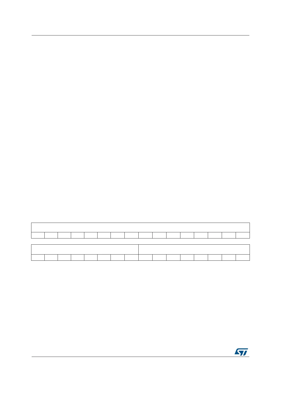
31 30 29 28 27 26 25 24 23 22 21 20 19 18 17 16
Reserved
1514131211109876543210
Reserved REGION[7:0]
rw rw rw rw rw rw rw rw
Bits 31:8 Reserved, forced by hardware to 0.
Bits 7:0 REGION[7:0]: MPU region
These bits indicate the MPU region referenced by the MPU_RBAR and MPU_RASR registers.
The MPU supports 8 memory regions, so the permitted values of this field are 0-7.
Normally, you write the required region number to this register before accessing the
MPU_RBAR or MPU_RASR. However you can change the region number by writing to the
MPU_RBAR register with the VALID bit set to 1, see MPU region base address register
(MPU_RBAR). This write updates the value of the REGION field.

Table of Contents

Other manuals for ST STM32H7 Series

Question and Answer IconNeed help?

Do you have a question about the ST STM32H7 Series and is the answer not in the manual?

ST STM32H7 Series Specifications

General IconGeneral
BrandST
ModelSTM32H7 Series
CategoryComputer Hardware
LanguageEnglish

Summary

About this document

Typographical Conventions

Defines formatting used in the document for clarity.

List of Abbreviations for Registers

Provides a list of abbreviations used in register descriptions for quick reference.

STM32 Cortex-M4 Processor Overview

Introduces the STM32 Cortex-M4 processor's architecture and key features.

The Cortex-M4 Processor

Programmer's Model

Describes registers, modes, and privilege levels for software execution.

Memory Model

Details the processor's memory map, access behavior, and bit-banding features.

Exception Model

Explains exception states, types, priorities, and handling mechanisms.

Fault Handling

Covers fault types, escalation, status registers, and lockup conditions.

Power Management

Describes mechanisms for entering and exiting low-power sleep modes.

The STM32 Cortex-M4 Instruction Set

Instruction Set Summary

Lists supported Cortex-M4 instructions and their organization.

Memory Access Instructions

Details instructions for loading and storing data from/to memory.

General Data Processing Instructions

Explains instructions for arithmetic, logical, and data manipulation.

Multiply and Divide Instructions

Describes instructions for multiplication and division operations.

Floating-Point Instructions

Details instructions for FPU operations, including VFPv4-SP extension.

Miscellaneous Instructions

Covers instructions like breakpoints, barriers, and supervisor calls.

Core Peripherals

About the STM32 Cortex-M4 Core Peripherals

Introduces the core peripherals accessible via the Private Peripheral Bus (PPB).

Memory Protection Unit (MPU)

Explains the MPU for memory region definition and access control.

Nested Vectored Interrupt Controller (NVIC)

Describes the NVIC for managing interrupts and exceptions with priority levels.

System Control Block (SCB)

Details registers for system control, configuration, and exception reporting.

SysTick Timer (STK)

Explains the 24-bit SysTick timer for system timing and RTOS ticks.

Floating Point Unit (FPU)

Describes the FPU for single-precision floating-point operations.

Revision History

Related product manuals