EasyManua.ls Logo

ST STM32H7 Series User Manual

ST STM32H7 Series
262 pages
To Next Page IconTo Next Page
To Previous Page IconTo Previous Page
Page #199 background imageLoading...
Page #199 background image
PM0214 Rev 9 199/262
PM0214 Core peripherals
261
4.2.4 MPU design hints and tips
To avoid unexpected behavior, disable the interrupts before updating the attributes of a
region that the interrupt handlers might access.
Ensure software uses aligned accesses of the correct size to access MPU registers:
• Except for the RASR, it must use aligned word accesses
• For the RASR it can use byte or aligned halfword or word accesses.
The processor does not support unaligned accesses to MPU registers.
When setting up the MPU, and if the MPU has previously been programmed, disable
unused regions to prevent any previous region settings from affecting the new MPU setup.
Recommended MPU configuration
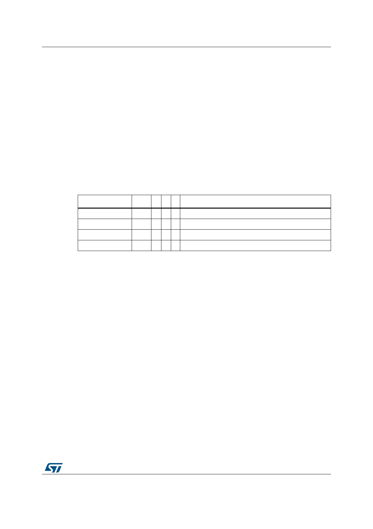
The STM32 microcontroller system has only a single processor, so you should program the
MPU as follows:
In STM32 implementations, the shareability and cache policy attributes do not affect the
system behavior. However, using these settings for the MPU regions can make the
application code more portable. The values given are for typical situations.
Note: The MPU attributes don't affect DMA data accesses to the memory/peripherals address
spaces. therefore, in order to protect the memory areas against inadvertent DMA accesses,
the MPU must control the SW/CPU access to the DMA registers.
Table 42. Memory region attributes for STM32
Memory region TEX C B S Memory type and attributes
Flash memory b000 1 0 0 Normal memory, Non-shareable, write-through
Internal SRAM b000 1 0 1 Normal memory, Shareable, write-through
External SRAM b000 1 1 1 Normal memory, Shareable, write-back, write-allocate
Peripherals b000 0 1 1 Device memory, Shareable

Table of Contents

Other manuals for ST STM32H7 Series

Question and Answer IconNeed help?

Do you have a question about the ST STM32H7 Series and is the answer not in the manual?

ST STM32H7 Series Specifications

General IconGeneral
BrandST
ModelSTM32H7 Series
CategoryComputer Hardware
LanguageEnglish

Summary

About this document

Typographical Conventions

Defines formatting used in the document for clarity.

List of Abbreviations for Registers

Provides a list of abbreviations used in register descriptions for quick reference.

STM32 Cortex-M4 Processor Overview

Introduces the STM32 Cortex-M4 processor's architecture and key features.

The Cortex-M4 Processor

Programmer's Model

Describes registers, modes, and privilege levels for software execution.

Memory Model

Details the processor's memory map, access behavior, and bit-banding features.

Exception Model

Explains exception states, types, priorities, and handling mechanisms.

Fault Handling

Covers fault types, escalation, status registers, and lockup conditions.

Power Management

Describes mechanisms for entering and exiting low-power sleep modes.

The STM32 Cortex-M4 Instruction Set

Instruction Set Summary

Lists supported Cortex-M4 instructions and their organization.

Memory Access Instructions

Details instructions for loading and storing data from/to memory.

General Data Processing Instructions

Explains instructions for arithmetic, logical, and data manipulation.

Multiply and Divide Instructions

Describes instructions for multiplication and division operations.

Floating-Point Instructions

Details instructions for FPU operations, including VFPv4-SP extension.

Miscellaneous Instructions

Covers instructions like breakpoints, barriers, and supervisor calls.

Core Peripherals

About the STM32 Cortex-M4 Core Peripherals

Introduces the core peripherals accessible via the Private Peripheral Bus (PPB).

Memory Protection Unit (MPU)

Explains the MPU for memory region definition and access control.

Nested Vectored Interrupt Controller (NVIC)

Describes the NVIC for managing interrupts and exceptions with priority levels.

System Control Block (SCB)

Details registers for system control, configuration, and exception reporting.

SysTick Timer (STK)

Explains the 24-bit SysTick timer for system timing and RTOS ticks.

Floating Point Unit (FPU)

Describes the FPU for single-precision floating-point operations.

Revision History

Related product manuals