EasyManua.ls Logo

ST STM32H7 Series User Manual

ST STM32H7 Series
262 pages
To Next Page IconTo Next Page
To Previous Page IconTo Previous Page
Page #213 background imageLoading...
Page #213 background image
PM0214 Rev 9 213/262
PM0214 Core peripherals
261
4.3.5 Interrupt clear-pending register x (NVIC_ICPRx)
Address offset: 0x280 + 0x04 * x, (x = 0 to 7)
Reset value: 0x0000 0000
Required privilege: Privileged
NVIC_ICPR0 bits 0 to 31 are for interrupt 0 to 31, respectively
NVIC_ICPR1 bits 0 to 31 are for interrupt 32 to 63, respectively
....
NVIC_ICPR6 bits 0 to 31 are for interrupt 192 to 223, respectively
NVIC_ICPR7 bits 0 to 15 are for interrupt 224 to 239, respectively
Note: The number of interrupts is product-dependent. Refer to reference manual/datasheet of
relevant STM32 product for related information.
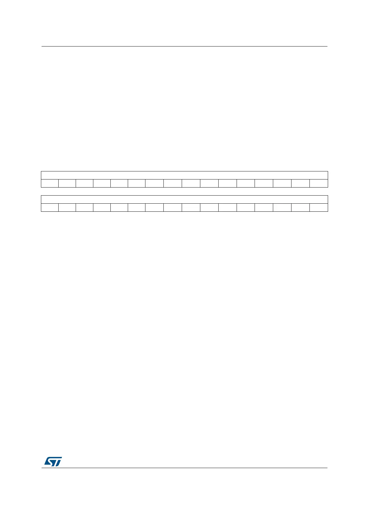
31 30 29 28 27 26 25 24 23 22 21 20 19 18 17 16
CLRPEND[31:16]
rc_w1 rc_w1 rc_w1 rc_w1 rc_w1 rc_w1 rc_w1 rc_w1 rc_w1 rc_w1 rc_w1 rc_w1 rc_w1 rc_w1 rc_w1 rc_w1
1514131211109876543210
CLRPEND[15:0]
rc_w1 rc_w1 rc_w1 rc_w1 rc_w1 rc_w1 rc_w1 rc_w1 rc_w1 rc_w1 rc_w1 rc_w1 rc_w1 rc_w1 rc_w1 rc_w1
Bits 31:0 CLRPEND: Interrupt clear-pending bits
Write:
0: No effect
1: Removes the pending state of an interrupt
Read:
0: Interrupt is not pending
1: Interrupt is pending
Writing 1 to an ICPR bit does not affect the active state of the corresponding interrupt.
Bits 16 to 31 of the NVIC_ICPR7 register are reserved.

Table of Contents

Other manuals for ST STM32H7 Series

Question and Answer IconNeed help?

Do you have a question about the ST STM32H7 Series and is the answer not in the manual?

ST STM32H7 Series Specifications

General IconGeneral
BrandST
ModelSTM32H7 Series
CategoryComputer Hardware
LanguageEnglish

Summary

About this document

Typographical Conventions

Defines formatting used in the document for clarity.

List of Abbreviations for Registers

Provides a list of abbreviations used in register descriptions for quick reference.

STM32 Cortex-M4 Processor Overview

Introduces the STM32 Cortex-M4 processor's architecture and key features.

The Cortex-M4 Processor

Programmer's Model

Describes registers, modes, and privilege levels for software execution.

Memory Model

Details the processor's memory map, access behavior, and bit-banding features.

Exception Model

Explains exception states, types, priorities, and handling mechanisms.

Fault Handling

Covers fault types, escalation, status registers, and lockup conditions.

Power Management

Describes mechanisms for entering and exiting low-power sleep modes.

The STM32 Cortex-M4 Instruction Set

Instruction Set Summary

Lists supported Cortex-M4 instructions and their organization.

Memory Access Instructions

Details instructions for loading and storing data from/to memory.

General Data Processing Instructions

Explains instructions for arithmetic, logical, and data manipulation.

Multiply and Divide Instructions

Describes instructions for multiplication and division operations.

Floating-Point Instructions

Details instructions for FPU operations, including VFPv4-SP extension.

Miscellaneous Instructions

Covers instructions like breakpoints, barriers, and supervisor calls.

Core Peripherals

About the STM32 Cortex-M4 Core Peripherals

Introduces the core peripherals accessible via the Private Peripheral Bus (PPB).

Memory Protection Unit (MPU)

Explains the MPU for memory region definition and access control.

Nested Vectored Interrupt Controller (NVIC)

Describes the NVIC for managing interrupts and exceptions with priority levels.

System Control Block (SCB)

Details registers for system control, configuration, and exception reporting.

SysTick Timer (STK)

Explains the 24-bit SysTick timer for system timing and RTOS ticks.

Floating Point Unit (FPU)

Describes the FPU for single-precision floating-point operations.

Revision History

Related product manuals