EasyManua.ls Logo

ST STM32H7 Series User Manual

ST STM32H7 Series
262 pages
To Next Page IconTo Next Page
To Previous Page IconTo Previous Page
Page #248 background imageLoading...
Page #248 background image
Core peripherals PM0214
248/262 PM0214 Rev 9
4.5.2 SysTick reload value register (STK_LOAD)
Address offset: 0x04
Reset value: 0x0000 0000
Required privilege: Privileged
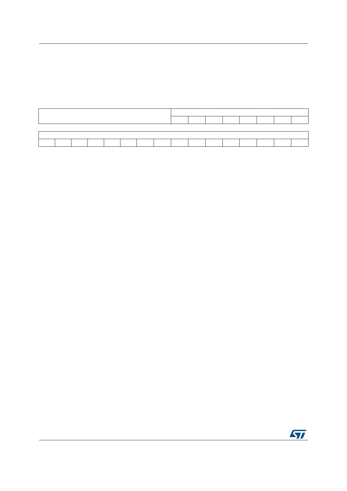
31 30 29 28 27 26 25 24 23 22 21 20 19 18 17 16
Reserved
RELOAD[23:16]
rw rw rw rw rw rw rw rw
1514131211109876543210
RELOAD[15:0]
rw rw rw rw rw rw rw rw rw rw rw rw rw rw rw rw
Bits 31:24 Reserved, must be kept cleared.
Bits 23:0 RELOAD: RELOAD value
The LOAD register specifies the start value to load into the STK_VAL register when the
counter is enabled and when it reaches 0.
Calculating the RELOAD value
The RELOAD value can be any value in the range 0x00000001-0x00FFFFFF. A start value of
0 is possible, but has no effect because the SysTick exception request and COUNTFLAG are
activated when counting from 1 to 0.
The RELOAD value is calculated according to its use:
l To generate a multi-shot timer with a period of N processor clock cycles, use a RELOAD
value of N-1. For example, if the SysTick interrupt is required every 100 clock pulses, set
RELOAD to 99.
l To deliver a single SysTick interrupt after a delay of N processor clock cycles, use a
RELOAD of value N. For example, if a SysTick interrupt is required after 100 clock
pulses, set RELOAD to 99.

Table of Contents

Other manuals for ST STM32H7 Series

Question and Answer IconNeed help?

Do you have a question about the ST STM32H7 Series and is the answer not in the manual?

ST STM32H7 Series Specifications

General IconGeneral
BrandST
ModelSTM32H7 Series
CategoryComputer Hardware
LanguageEnglish

Summary

About this document

Typographical Conventions

Defines formatting used in the document for clarity.

List of Abbreviations for Registers

Provides a list of abbreviations used in register descriptions for quick reference.

STM32 Cortex-M4 Processor Overview

Introduces the STM32 Cortex-M4 processor's architecture and key features.

The Cortex-M4 Processor

Programmer's Model

Describes registers, modes, and privilege levels for software execution.

Memory Model

Details the processor's memory map, access behavior, and bit-banding features.

Exception Model

Explains exception states, types, priorities, and handling mechanisms.

Fault Handling

Covers fault types, escalation, status registers, and lockup conditions.

Power Management

Describes mechanisms for entering and exiting low-power sleep modes.

The STM32 Cortex-M4 Instruction Set

Instruction Set Summary

Lists supported Cortex-M4 instructions and their organization.

Memory Access Instructions

Details instructions for loading and storing data from/to memory.

General Data Processing Instructions

Explains instructions for arithmetic, logical, and data manipulation.

Multiply and Divide Instructions

Describes instructions for multiplication and division operations.

Floating-Point Instructions

Details instructions for FPU operations, including VFPv4-SP extension.

Miscellaneous Instructions

Covers instructions like breakpoints, barriers, and supervisor calls.

Core Peripherals

About the STM32 Cortex-M4 Core Peripherals

Introduces the core peripherals accessible via the Private Peripheral Bus (PPB).

Memory Protection Unit (MPU)

Explains the MPU for memory region definition and access control.

Nested Vectored Interrupt Controller (NVIC)

Describes the NVIC for managing interrupts and exceptions with priority levels.

System Control Block (SCB)

Details registers for system control, configuration, and exception reporting.

SysTick Timer (STK)

Explains the 24-bit SysTick timer for system timing and RTOS ticks.

Floating Point Unit (FPU)

Describes the FPU for single-precision floating-point operations.

Revision History

Related product manuals