Instruction Manual
for
AS380 Series Elevator Integrated Drive Controller
139
to set each floor of each elevator is service floor or not. Click each small button will change color
of horizontal line within it (the blue mean that floor is service floor, having no color means non-
service floor).
Finally, click [No.1], [No.2] button one by one in the bottom of interface to transmit the data to
group control board. With the above example, first click 3# elevator's and 4# elevator's 01
floors(-2 floor) and 2nd floors(-1 floor) button to no color, then click [No.3 ] button to wait
communication over, then click [No.4]button, after waiting the communication over, setting
completion.
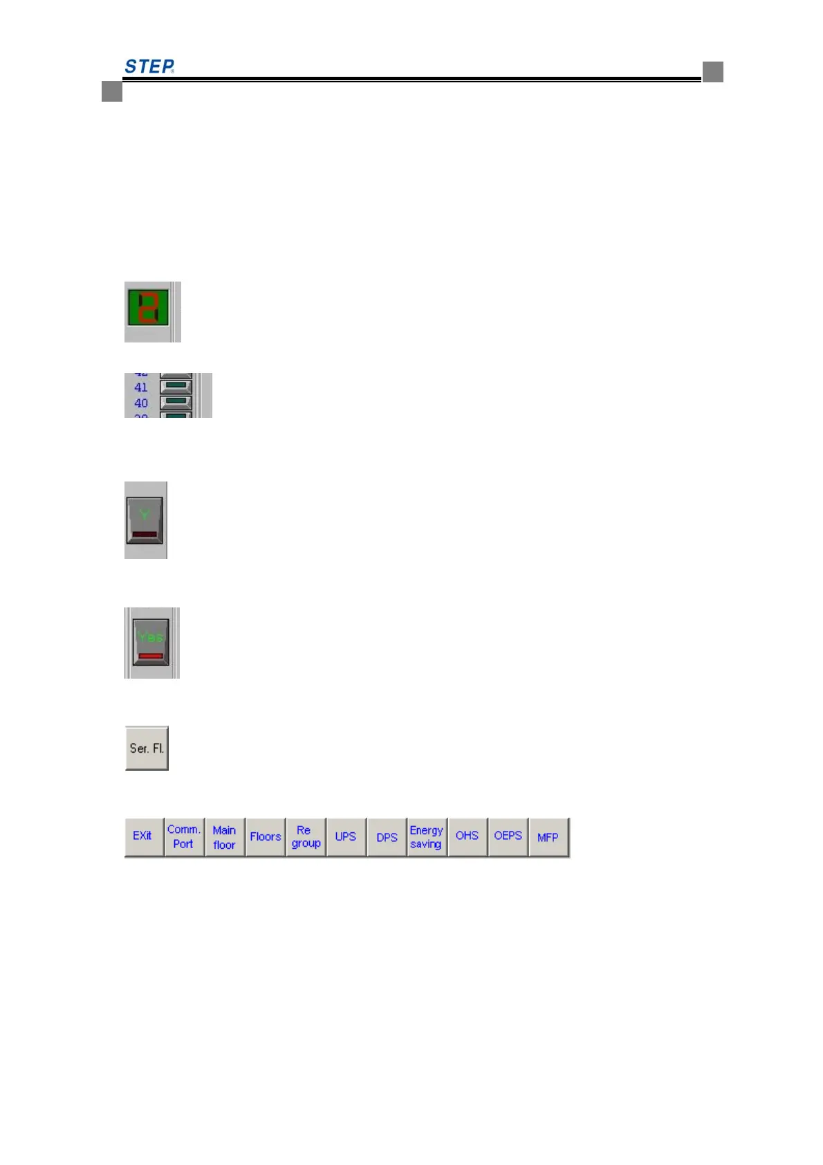
5. Setting interface pattern
The elevator number means the elevator serial number in the group. The diagram
example means No.2 elevator.
The choice button used for set service, instruction service, Up Call service and
Down Call service. The numeral of the left side means floor number. Button's middle line blue
means that floor is service floor, having no color means non- service floor. Data at the left side
means the floor number in the group (bottom floor is 1) .
The choice button used for setting teams in the group control. The red color of middle line
of button means that elevator is divided into X team when team grouping is valid , light color
means Y team.
The choice button used for setting whether that elevator runs or not when urgent power
supply is on. Red color of middle line within button means that elevator keep on running when the
urgent power supply is valid, light color means movement stops.
The service floor switch scheme prompt dialog box. This group system has two service
floors switch scheme in total. The diagram example mean current interface is setting instruction
service floor of scheme 1.
The group service specification order press button
[Exit]- Exit parameter setting program
[Comm. Port] – Set communication port
[Group control home floor] – set group control home floor
[Group control landing] – set group control landing.
[Group partition] set group partitions. Need to set each elevator grouping status before setting
group partitions.(The x group or Y group)
 Loading...