Instruction Manual
for
AS380 Series Elevator Integrated Drive Controller
141
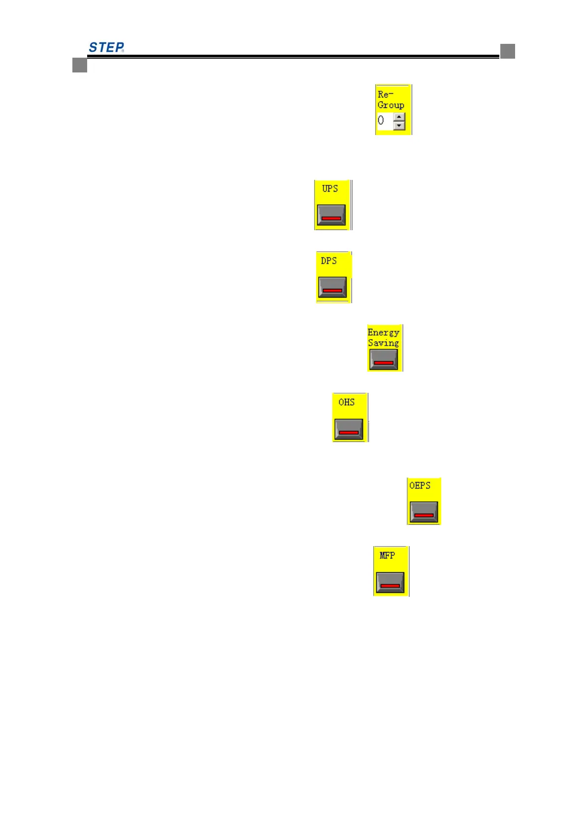
(4)The group partitions specification setting: If group of partition functions function is on, set
each elevator into team status first. Click the interface left side
button to change the
color of middle line of button to mean whether valid group of partition functions(have no
the color means invalid for that function, red means valid for that function).when selection
finished, click [Re group] set button in the bottom of interface.
(5) On-duty peak specification setting: After clicking
button to make this function valid
or not, click [UPS] button underneath of interface for command button setting.
(6) Off-duty peak specification setting: After clicking
button to make this function valid
or not, click [DPS] button underneath of interface.
(7)Energy saving running specification setting: After clicking
button to make this
function valid or not, click [Energy saving] button underneath of interface.
(8)Separate wait specification setting: After clicking
button to make this function
valid or not, click [OHS] button underneath of interface
(9)The urgent power supply running setting: If set the urgent power supply running function,
first set each elevator run or not when at urgent power supply .Click
button, after
making valid or invalid choice of that function, click [OEPS] button underneath of interface.
(10)Return the home floor specification setting: After clicking
button to make this
function valid or not, click [MFP] button underneath of interface.
(11)The non- service floor control specification setting: Unless there is special request, don't
need generally to set this specification. This system has total two service floor control
projects to provide a choice, controlled differently by two switches. When a switch ON,
the elevator run with project 1 service floor specification. When another switch ON, the
elevator run with project 2 service floor specifications. Two switches can't switch ON
simultaneously. But when two switches are OFF, the elevator carries out the normal service
floor movement. In two sets of projects, all can set the instruction service floor, up Call
service floor and Down Call service floor respectively. Right underneath of the interface
there is six buttons: [NS-1 Car],[NS-1 Up],[NS-1 Down],[NS-2Car],[NS-2 Up],[NS-2
Down] set respectively project 1's instruction service floor, project 1's Up Call service floor,
project 1's Down Call service floor and project 2's instruction service floor, project 2's Up
 Loading...