Instruction Manual
for
AS380 Series Elevator Integrated Drive Controller
83
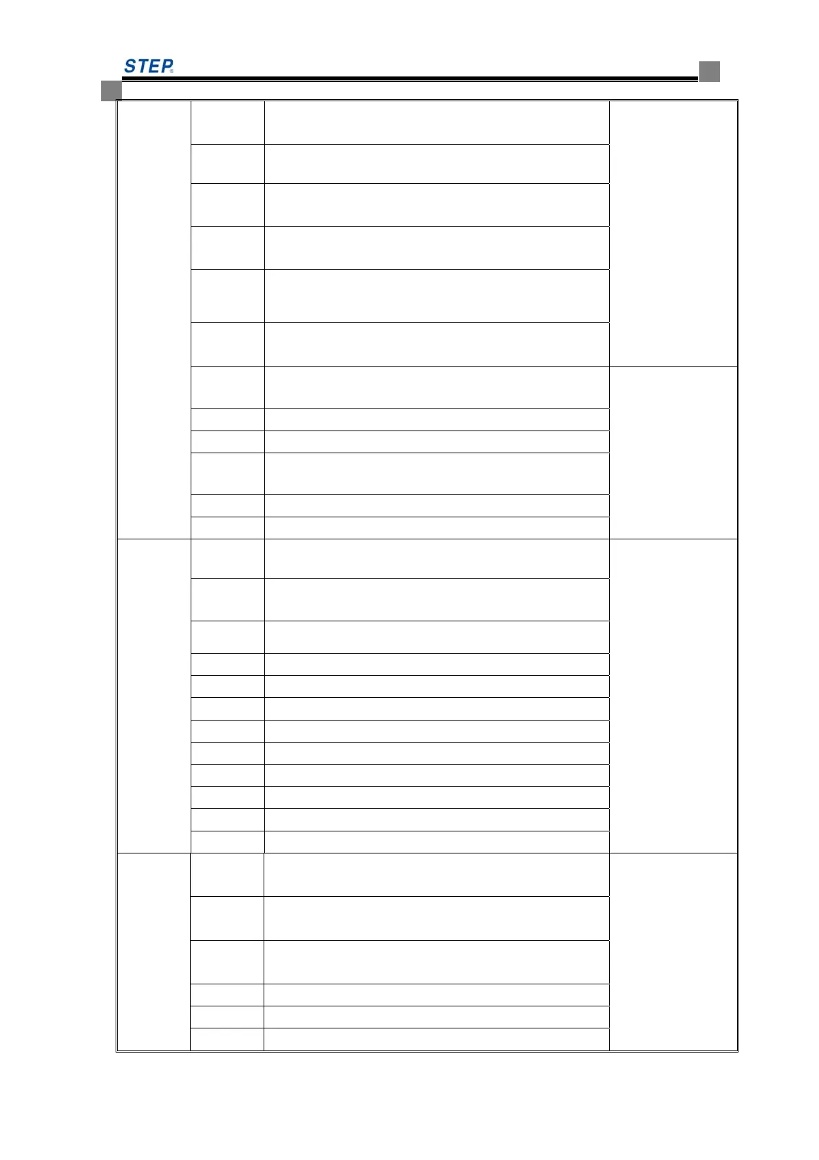
L3 band brake contactor contact input signal ( contactor no
adhesion , light on)
light on means that
peripheral signal
ok for inspection
running
L4 band brake switch ( input point normal and light on)
L5 motor overheat( input point normal and light on)
L6 up limit switch ( compound) status signal
L7 down limit switch ( compound ) status signal
L8 inspection upward/downward signal( light on as signal
exist
L10 main contactor drive signal The internal status
as inspection
running. all six
light on one by one
when inspection
run normally.
L11 enable signal
L12 signal for moving up /down
L13 running signal feed from drive part
L14 band brake contactor drive signal
L15 speed curve given or not
LED 01
L1 down limit switch status- light off, no move down Hoist way switch
and leveling switch
status. Light on
means the
connection of
external input point
L2 down level-1 forced deceleration switch on-off
L3 down level-2 forced deceleration switch on-off
L4 down level-3 forced deceleration switch on-off
L5 down level-4 forced deceleration switch on-off
L6 up level-1 forced deceleration switch on-off
L7 up level-2 forced deceleration switch on-off
L8 up level-3 forced deceleration switch on-off
L9 up level-4 forced deceleration switch on-off
L10 up limit switch status- light off, do not move up
L11 up leveling switch on-off
L12 down leveling switch on-off
LED 02
L1 door lock relay ( X17/parameter setting-if no normal
light)
Quick car running
startup condition.
All these 11 light
on means the
peripheral signal
ok, the startup
condition for quick
car running is met
L2 )main contactor contact input signal ( contactor no
adhesion and light on)
L3 band brake contactor contact input signal( contact no
adhesion and light on)
L4 band brake switch
L5 motor overheating
L6 up limit switch ( compound) status signal
 Loading...