Instruction Manual
for
AS380 Series Elevator Integrated Drive Controller
84
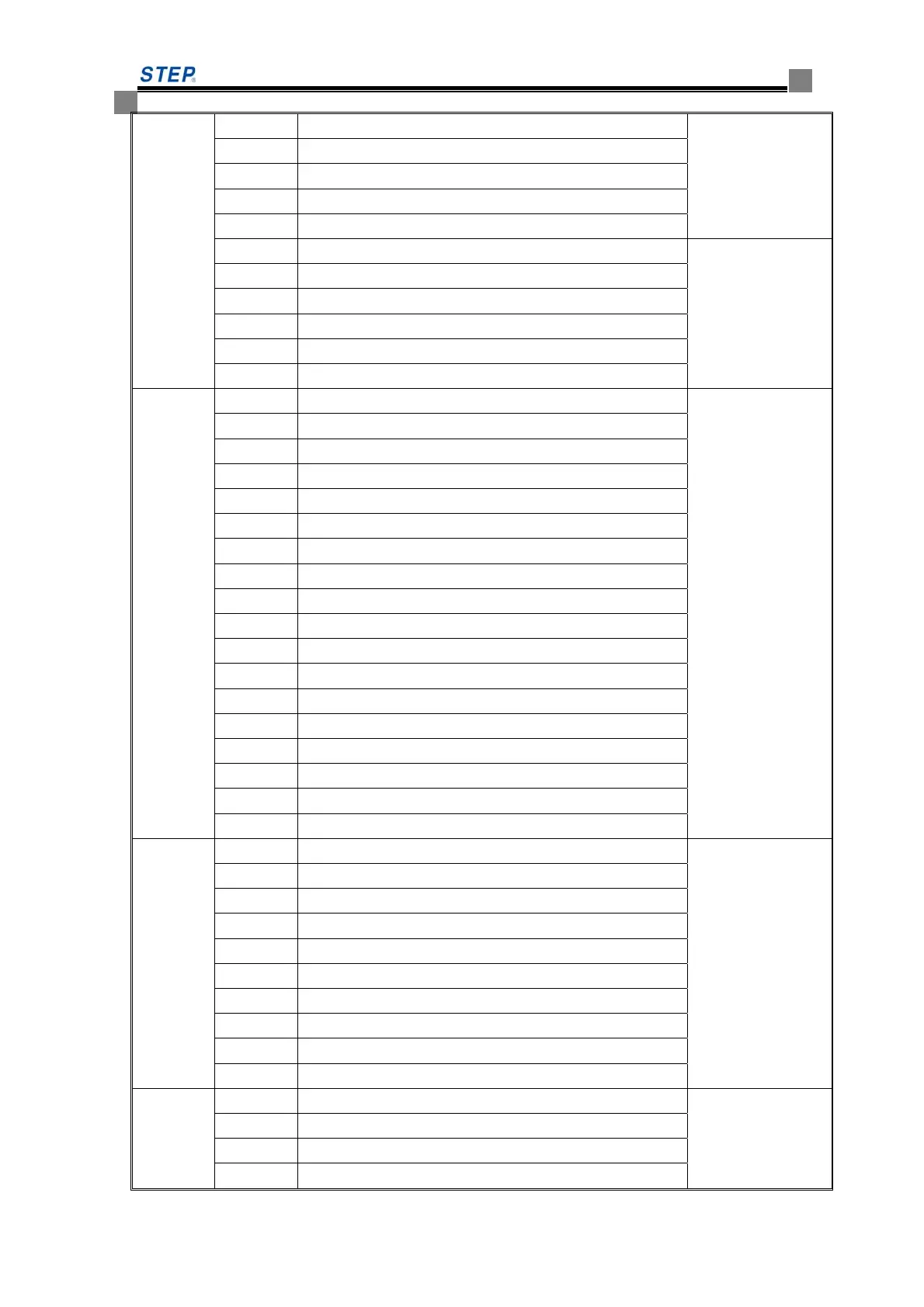
L7 down limit switch ( compound ) status signal
L8 door close limit switch signal ( front and rear door)
L9 light on when no internal startup fault exist
L10 front valid signal registration existed or not
L11 auto hi-speed status signal
L12 main contactor drive signal The internal status
of quick car
running. All six
light on one by one
when the quick car
run normally.
L13 enable signal
L14 up direction/down direction signal
L15 running signal feed from drive part
L16 band brake contactor drive signal
L17 speed curve given or not
LED 03
L1 front door open limit on-off Door open/close
signal. Light on
mean external
input point is
connected.
L2 front door close limit on-off
L3 rear door open limit on-off
L4 rear door close limit on-off
L5 front door safety edge switch on-off
L6 rear door safety edge switch on-off
L7 front door light curtain switch on-off
L8 rear door light curtain switch on-off
L9 overload switch on-off
L10 door open button signal
L11 door close button signal
L12 present floor door open signal
L13 light on when in attendant status or independent status
L14 light on when in firemen operation status
L15 front door open output
L16 front door close output
L17 rear door open output
L18 rear door close output
LED 04
L1 main contactor contact input on-off Contact inspection
signal, light on
mean external
signal connected.
L2 band brake contactor contact input on-off
L3 No 1 band brake inspection switch contact input on-off
L4 No 2 band brake inspection switch contact input on-off
L5 safety circuit high-voltage point input on-off
L6 safety circuit relay contact input on-off
L7 door lock circuit high-voltage point input on-off
L8 door lock relay contact point input on-off
L10 main contactor drive output
L11 band brake contactor drive output
LED 05
L1 down limit switch status Main input signal
logic status
L2 down level-1 forced deceleration switch status
L3 down level-2 forced deceleration switch status
L4 down level-3 forced deceleration switch status
 Loading...