3-12
17 363 02 0320
System description
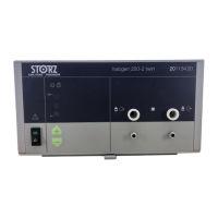
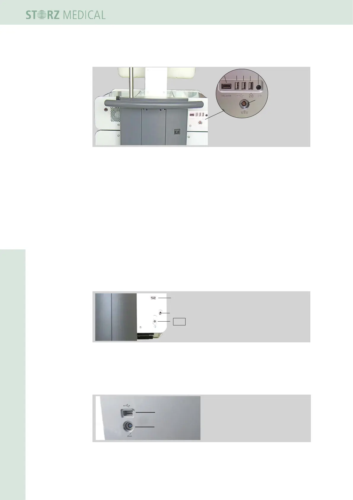
3.5.2 Connectors
1 HDMI
2 USB1
3 USB2
4 USB3 (2.0)
5 Audio
6 LAN
1
2
3
4 5
6
Fig. 3-16 Rear side - connectors control module
Connectors Control module
The USB connectors serve as an interface for data input and output.
• Connect if required
– a USB memory stick which supports the USB V1.1 protocol
– a PCL3-capable printer
– a USB mouse
– a USB keyboard
The USB3 connector (right) supports USB protocol 2.0 (see
Chapter 4.5.16 sOftWare
updates).
The printer must be authorised as a medical product acc. to EN IEC 60601.
The LAN is used as a connector for a DICOM-capable network.
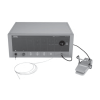
Connectors F-SW module
1 USB for software update
2 Bleeder valve
3 Water hose connector
1
2
3
Fig. 3-17 Rear side - connectors F-SW module
Connect an USB memory stick to the USB connector, which, which supports the USB
protocol V1.1 unterstützt - for software update.
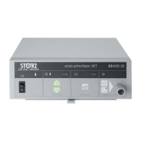
Connectors R-SW module rear side
1
2
1 USB for software update
2 Connector for foot switch
Fig. 3-18 Rear side - connectors R-SW module
Connect an USB memory stick to the USB connector, which, which supports the USB
protocol V1.1 - for software update.