3-24
17 363 02 0320
System description
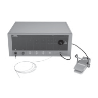
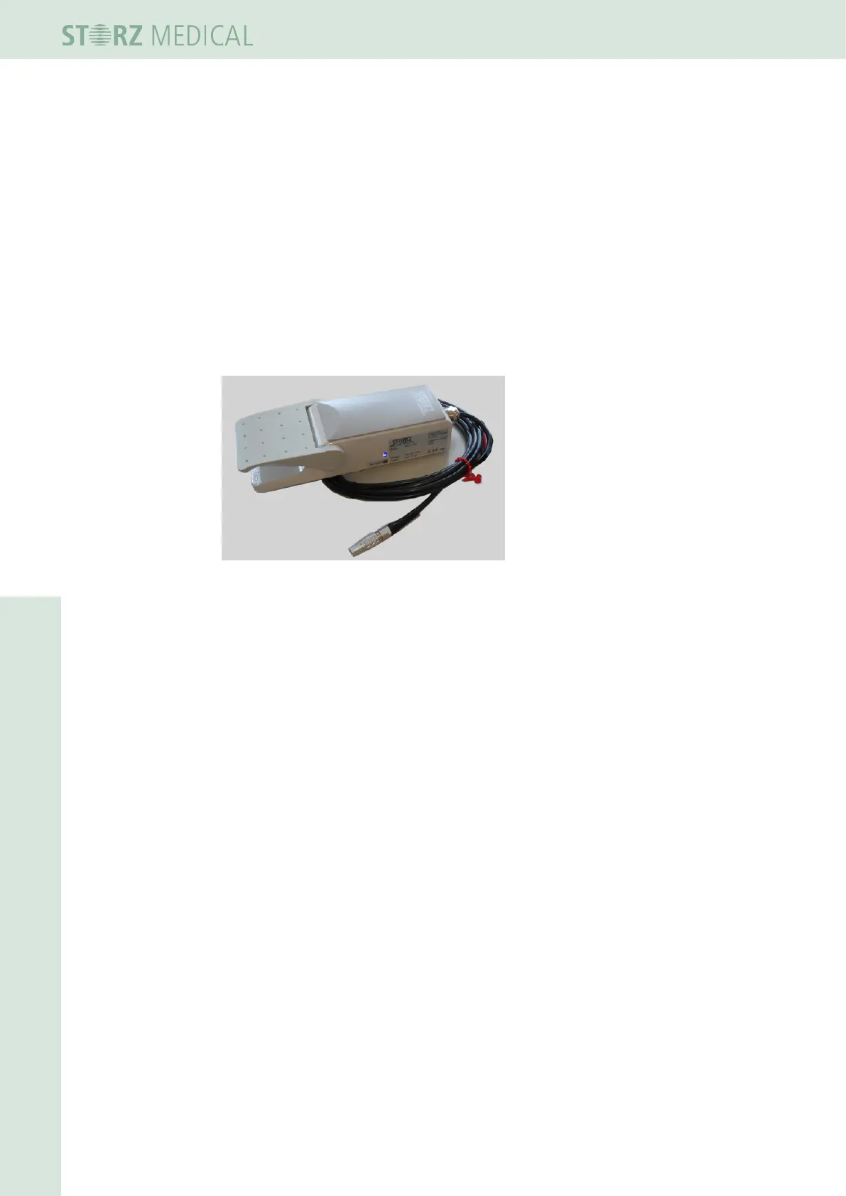
3.7.6 Connecting the foot switch
The connector for an optional foot switch (article no. 10103) is located on the rear of
the R-SW module.
• Plug the plug of the foot switch into the connector on the rear of the R-SW
module.
Pressing the connected foot switch allows the ultrasound image to be frozen (saving
a US image); the image on the display can be traversed again once the foot switch is
released.
Treatment with the VACU-ACTOR can be activated and deactivated with the aid of
the foot switch.
Fig. 3-37 Optional Karl Storz foot switch