5-14 Sun StorEdge 3000 Family Installation, Operation, and Service Manual • May 2004
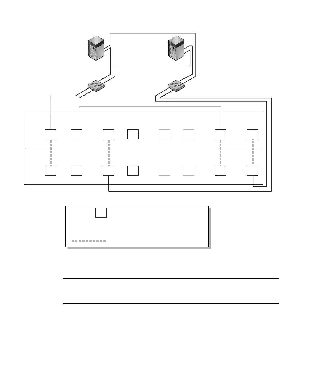
FIGURE 5-2 A Point-to-Point Configuration With a Dual-Controller Sun StorEdge 3511 FC Array and Two
Switches
Note – These illustrations show the default controller locations; however, the
primary controller and secondary controller locations can occur in either slot and
depend on controller resets and controller replacement operations.
TABLE 5-1 summarizes the primary and secondary host IDs assigned to logical drives
0 and 1, based on
FIGURE 5-1 and FIGURE 5-2.
: Host port on channel number N
PID 40 / PID43 : Host IDs on primary controller
SID 45 / SID46 : Host IDs on secondary controller
N/A : Not applicable (no ID on that controller)
: Port bypass circuit
N/A
Switch 0
Server 0
Switch 1
Server 1
N
PID 40 PID 43
N/A
SID 45
N/A
N/A SID 46
Map LG0 to PIDs 40 and 43 Map LG1 to SIDs 45 and 46
A
A
C
C
H
H
G
G