Sun Microelectronics
154
UltraSPARC User’s Manual
• ID<15:10>: Manufacturer identification.
• ID<9:4>: Module type.
• ID<3:0>: Module revision number.
8.3.3.2 UPA Configuration Register
The UPA_CONFIG Register can be accessed at ASI 4A
16
, VA=0. This is a 64-bit
register; non-64-bit aligned accesses cause a
mem_address_not_aligned
trap. See
Table 10-1, “Machine State After Reset and in RED_state,” on page 172 for the
state of this register after reset. Figure 8-2 shows the UPA_CONFIG register for
UltraSPARC-I. Figure 8-3 shows the UPA_CONFIG register for UltraSPARC-II.
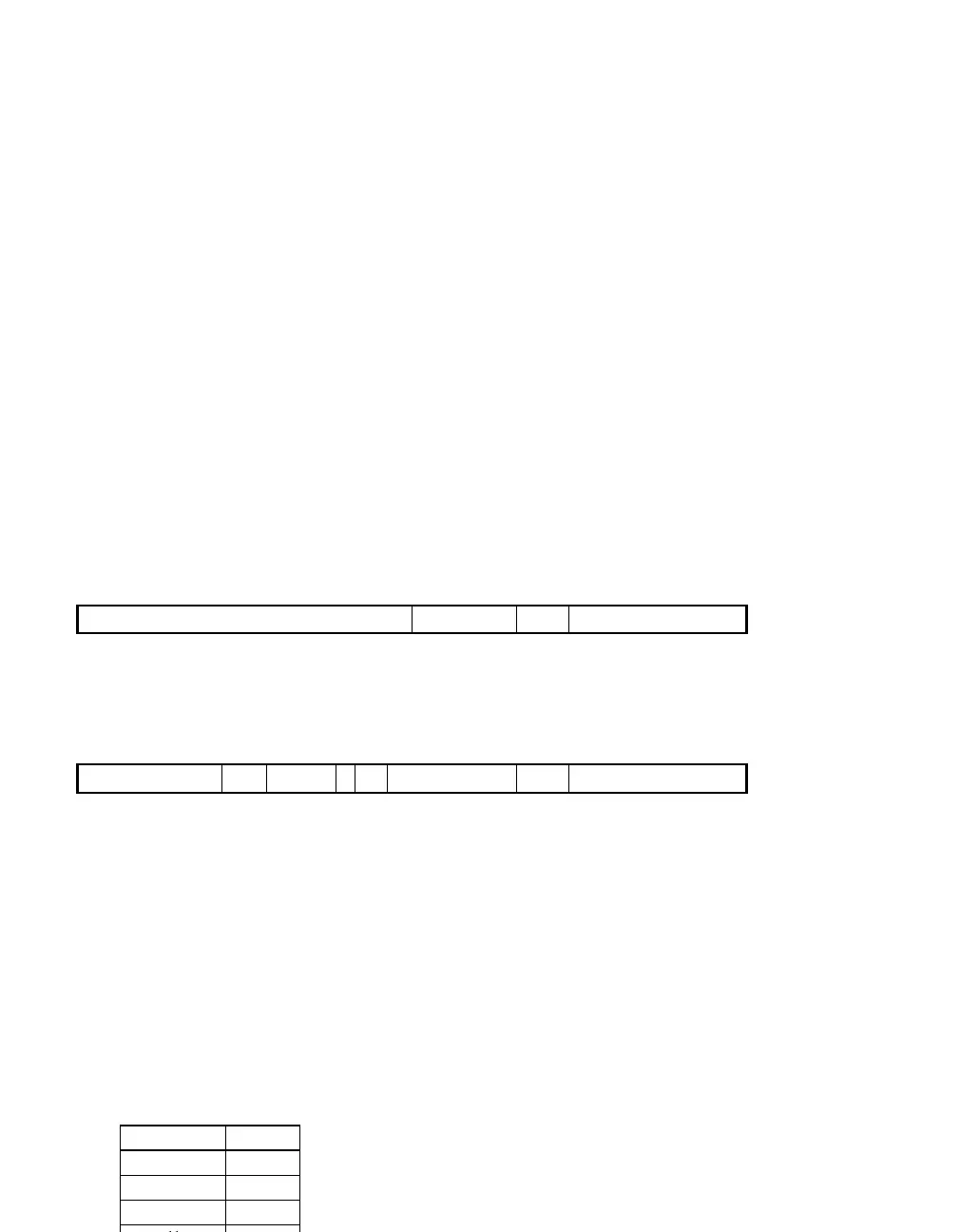
Figure 8-2 UPA_CONFIG Register (UltraSPARC-I)
Figure 8-3 UPA_CONFIG Register (UltraSPARC-II)
MCAP (UltraSPARC-II): Implementation-dependent module capability bits.
Software can use these bits to determine the processor module speed
capability. These bits are hard-wired or jumpered and brought on chip.
MCAP is a read only field; writes to these bits have no effect.
CLK_MODE (UltraSPARC-II): Encoded ratio of UPA system clock frequency to
processor internal clock frequency. This is a read only field; writes to
these bits have no effect. CLK_MODE is encoded as follows:
CLK_MODE Ratio
00 2 : 1
01 3 : 1
10 4 : 1
11 —
63 29 2130 22 17 16 0
— PCON MID PCAP
32
21
33
22 17 16 0
353637383943 42
63
— PCON MID PCAPELIME$CLK_MODEMCAP
Artisan Technology Group - Quality Instrumentation ... Guaranteed | (888) 88-SOURCE | www.artisantg.com
 Loading...