Sun Microelectronics
73
UltraSPARC External Interfaces 7
7.1 Introduction
This chapter describes the interaction of the UltraSPARC CPU with the external
cache (E-Cache), the UltraSPARC Data Buffer (UDB), and the remainder of the
system.
See Appendix E, “Pin and Signal Descriptions,” for a description of the external
interface pins and signals (including buses, control signals, clock inputs, etc.)
See the UltraSPARC-I Data Sheet for information about the electrical and mechan-
ical characteristics of the processor, including pin and pad assignments. The Bib-
liography on page 363 describes how to obtain the data sheet.
7.2 Overview of UltraSPARC External Interfaces
Figure 7-1 on page 74 shows the UltraSPARC’s main interfaces. Model-dependent
interface lengths are labeled in italics, instead of being numbered; Table 7-3 shows
the number of bits in each labeled interface.
A typical module includes an E-Cache composed of the tag part and the data
part, both of which can be implemented using commodity RAMs. Separate ad-
dress and data buses are provided to and from the tag and data RAMs for in-
creased performance.
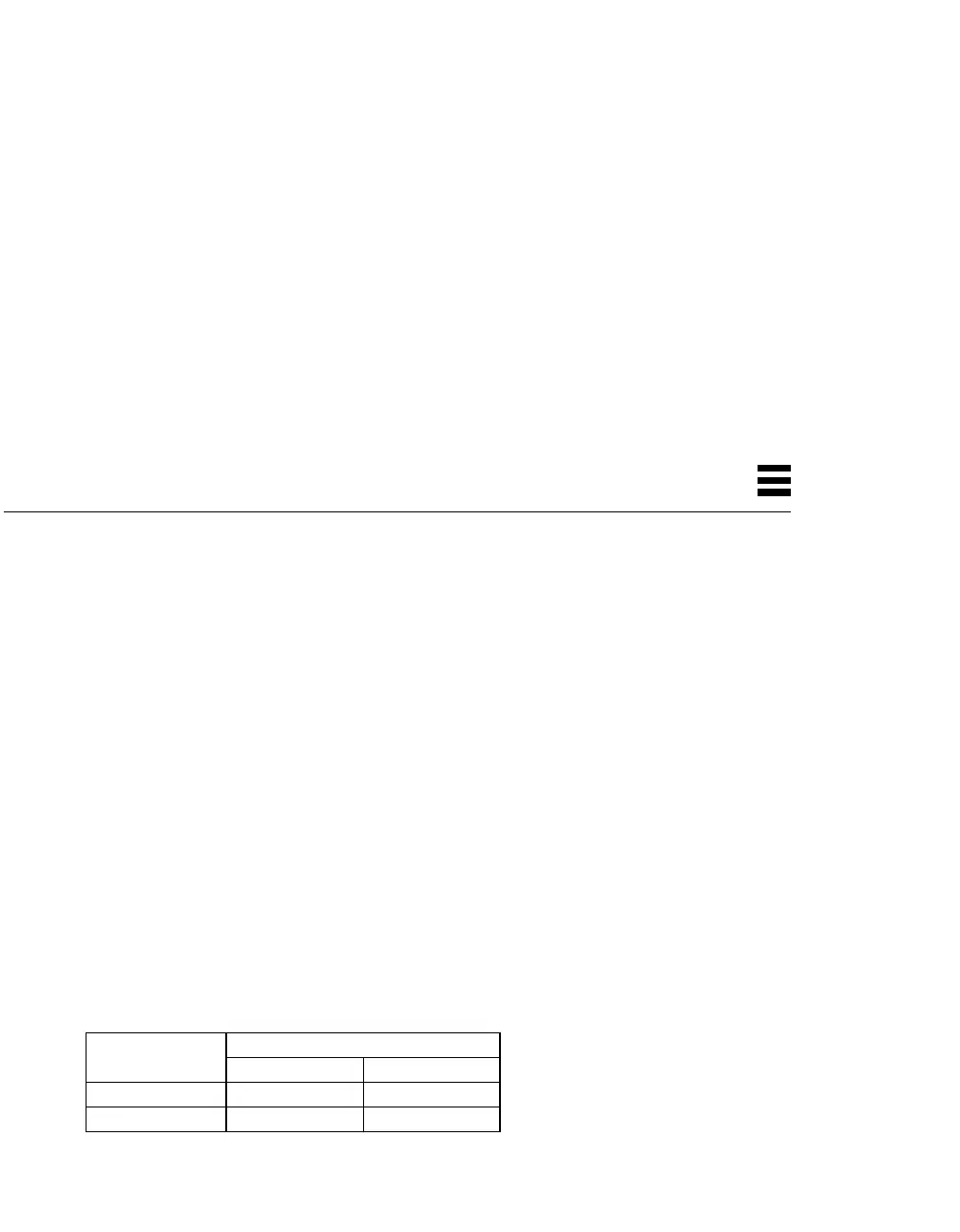
Table 7-1 Model-Dependent Interface Sizes
Number of Bits in Interface
Interface Label UltraSPARC-I UltraSPARC-II
E$TagAddrBits 16 18
E$DataAddrBits 18 20
Artisan Technology Group - Quality Instrumentation ... Guaranteed | (888) 88-SOURCE | www.artisantg.com
 Loading...