Sun Microelectronics
79
7. UltraSPARC External Interfaces
7.3.2.1 Coherent Read Hit (1–1–1 and 2–2 Modes)
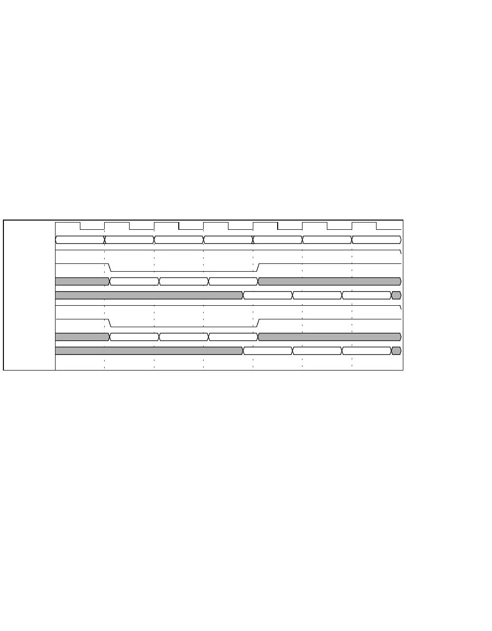
Figure 7-3 shows the 1–1–1 Mode timing for coherent reads that hit the E-Cache.
UltraSPARC makes no distinction between burst reads (which are supported by
some RAMs) and two consecutive reads; the signals used for a single read are du-
plicated for each subsequent read.
Figure 7-3 Timing for Coherent Read Hit (1–1–1 Mode)
The timing diagram shows three consecutive reads that hit the E-Cache. The con-
trol signal (TOE_L) and the address for the tag read (ECAT) as well as the control
signal (DOE_L) and the address for the data (ECAD) are shown to transition
shortly after the rising edge of the clock. Two cycles later, the data for both the
tag read and data read is back at the pins of the CPU shortly before the next ris-
ing edge (which meets the set up time and clock skew requirements). Notice that
the reads are fully pipelined; thus, full throughput is achieved. Three requests are
made before the data of the first request comes back, and the latency of each re-
quest is three cycles.
Figure 7-4 on page 80 shows the 2–2 Mode timing for three consecutive coherent
reads that hit the E-Cache. The control signal (TOE_L) and the address for the tag
read (ECAT) as well as the control signal (DOE_L) and the address for the data
(ECAD) are shown to transition shortly after the rising edge of the clock. One cy-
cle later, the data for both the tag read and data read is back at the pins of the
CPU shortly before the next rising edge (which meets the set up time and clock
skew requirements). Two requests are made before the data of the first request
comes back, and the latency of each request is two cycles.
CLK
CYCLE
0123456
TSYN_WR_L
R0 R1 R2
TOE_L
R0 R1 R2
ECAT
A0_tag A1_tag A2_tag
TDATA
D0_tag D1_tag D2_tag
DSYN_WR_L
R0 R1 R2
DOE_L R0 R1 R2
ECAD
A0_data A1_data A2_data
EDATA
D0_data D1_data D2_data
Artisan Technology Group - Quality Instrumentation ... Guaranteed | (888) 88-SOURCE | www.artisantg.com
 Loading...