Innagator | Technical Pack167
No.
Communica-
tion Category
Function
Category
Function Name Function Description
6 INTER-CAN BUS
HVESS-Moni-
tor storage
Real-time data
storage of
HVESS-Monitor
Operation data stored real-time in backstage
of HVESS-Monitor
7 INTER-CAN BUS Parameter
BMS parameter
BMU parameter
Read the current parameters displayed,
including the cell's overcharge, the system's
overcharge, the cell's over-discharge, the
system's system over-discharge, charging
overcurrent, discharging overcurrent, charg-
ing under temperature, discharging under
temperature, charging overtemperature,
dischargingundertemperature,dierential
voltage, etc.
8 Firmware
INTER-CAN BUS
rmwareupdate
Upgrade BMS and BMU via INTER-CAN BUS
9 Manufacture Manufacture
Extract relevant information such as product
serial number
10
PS CAN
Inverter infor-
mation
Information
Read and display inverter and parallel device
information
11 Firmware
PCS CAN BUS
rmwareupdate
Upgrade BMS and BMU via PCS CAN BUS
Function Description
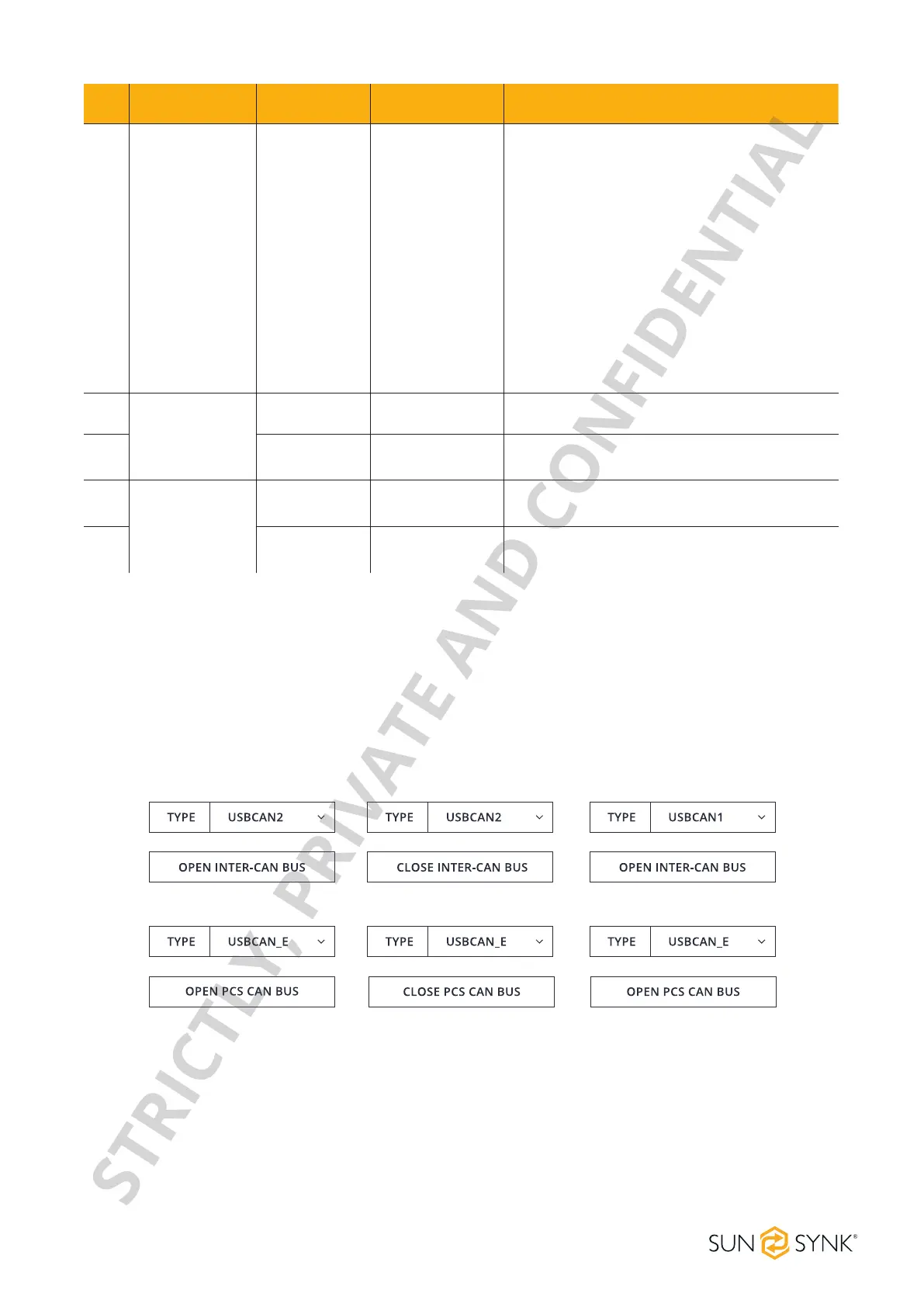
1. Insert the network cable into IN port, click the OPEN INTER-CAN BUS button to start the INTER-CAN com-
munication, and click the button again to stop such communication.
2. Insert the network cable into the PCS port, click the OPEN PCS CAN BUS button to start the INVERTER
CAN communication, and click the button again to stop such communication.
The default mode is Factory Mode. To display detailed information, change to Debug Mode and click the
Set button.
CAN Communication Conguration
Basic Information
STRICTLY, PRIVATE AND CONFIDENTIAL