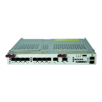
1/10 and 10-Gigabit Layer 2/3 Ethernet Switches User’s Manual
5-56
The Master switch manages the control plane traffic for all stacked switches. When the
current master switch fails, the backup master is then selected as the current master.
The Master selection algorithm is based on a priority configuration. If two switches have
the same priority, the switch with the lowest MAC address is selected as the Master
switch.
Enabling Stacking
By default, Supermicro switches act as stand-alone switches. This stand-alone default
facilitates using 10G Ethernet ports as Extrement Ethernet ports for uplinks.
When stacking is enabled the stacking ports are dedicated for stacking purposes.
Stacking can be enabled using the command stack with the switch identifier and
priority. The detailed command syntax is explained below.
NOTE: When stacking is enabled, the switch needs to be rebooted to make it effective.
NOTE: When a switch is acting as a stand-alone switch with stacking disabled, all physical
interfaces are numbered as 0/1 to 0/n. When the switch is in stacking mode, the interfaces
are numbered as <switch id>/1 to <switch id> / n. In non-stacking mode, the
switch ID is considered to be 0.
The interface numbers change between stacking and non-stacking cases due to the
switch ID. So configurations saved for stacking are not valid for non-stacking cases and
vice versa.
NOTE: If you choose stacking using the stack command from a non-stacking case, and the
configurations are already saved for restoring the switch, it will rename the configuration file
by adding a suffix _nonstack and will not restore this file when the switch reboots with
stacking enabled.
Similarily if you choose non-stacking using the no stack command from the stacking case,
and the configurations are already saved for restoring the switch, it will rename the
configuration file by adding a suffix _stack and will not restore this file when the switch
reboots with stacking disabled.
Adding Stacking Members
Connect the stacked switches using stacking cables. For better redundancy, connect
the switches daisy chained as shown in the diagram below (Figure 5-42). This chain
connectivity helps to maintain stacking in case a single link or switch fails.
Before connecting switches in stacking, make sure stacking is enabled in all switches
and that the switch identifier and priorities are all configured properly.
There is no other specifical configuration required to add stacked switches. If two
stacking-enabled switches connect through stacking cables, they form a stack.
NOTE: Do not use the same switch ID for multiple switches on the stack.
NOTE: Do not use the same switch ID for multiple switches on the stack.

 Loading...