92
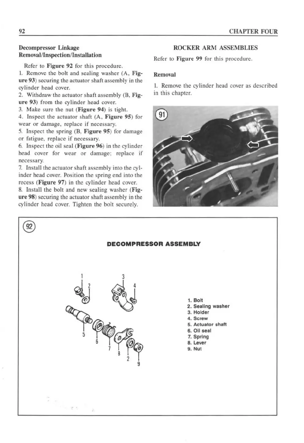
Decompressor Linkage
RemovalJInspectionJ
lnsta
ll
ation
Refer
to
Fi
gure
92
for this procedure.
1.
Remove the bolt and seali
ng
washer (A. Fig-
ur
e
93
) securing the ac
tu
ator shaft assembly in
th
e
cy
linder head cover.
2.
Withd raw the actuator shaft assembly (B, Fig-
ure 93) from the cyli
nd
er head cover.
3.
Make sure the nut (
I<
"igure 94) is tigh!.
4. Inspect the actuator shaft (A.
Figure
95)
fo
r
wear or damage. replace
if
necessary.
5. Inspect the spri
ng
(8.
Figure 95) for damage
or
fatigue. replace
if
necessary.
6.
Inspect
th
e oil seal (Fig
ur
e 96)
in
the cylinder
head cover f
or
wear
or
damage; replace if
necessary.
7.
InSlall the actuator shaft assembly into the cy
l-
inder head cover. Position the spring end into the
recess
(Fi
gure
97)
in
the
cy
linder head cover.
8.
In
stall the
bah
and ncw scaling washcr (Fig-
ure
98
) sccuring thc ac
tu
ator shaft asscmbly in the
cy
linder head cover. Tightcn the
boh
sccurely.
®
C
HAPTER
FOUR
ROCKER
ARM
ASSEl\'fBLIES
Refer to
Figure
99 for this procedure.
Removal
1.
Remove the cylinder head covcr as described
in
this chapter.
DECOMPRESSOR
ASSEMBLY
1. B
ol
l
2. Sealing waaher
3. Hotder
4. Screw
5. Actuator
s
haft
6.
011
aeat
7. Sprlng
8.
Lever
9.
Nut
 Loading...


