212
2.
Remove Ihe seal as desc
ri
bed in Chapler
Twelve.
3.
Di
sco
nn
ect thc a
il
e
rn
ator's 3-pin electrical
co
nn
ect
or
(Figure 4) co
nt
aining 3
ye
ll
ow wires
from
thc
vo
lt
age regulator located on the rear
fe
n
de
r.
4. Use an ohmmeter SCI at R x 10 and check for
continuity between each
stator
ye
ll
ow wire (Figure
1
),
5.
Ther
e should be continuity (low resistance). If
there is
no
co
nt
i
nu
ity (infinite resistance)
th
e stator
assembly
is
faulty and
mu
st
be
replaced as
desc
ri
bed in thi s chapter.
6.
Make sure a
ll
electrical
co
nnectors are
fr
ee
of
corrosion and arc tight.
7.
Reconnect Ihe alternator
's
3-p
in
electrical
connector (
Figu
re 4) containing 3
ye
ll
ow wires
10
thc
vo
lta
ge
r
eg
ulator.
8.
Make sure a
ll
electrical
co
nn
ectors
ar
e free
of
corrosion a
nd
are tight.
9.
In
stall
th
e scat as
de
scribed in Chapt
er
Twelve.
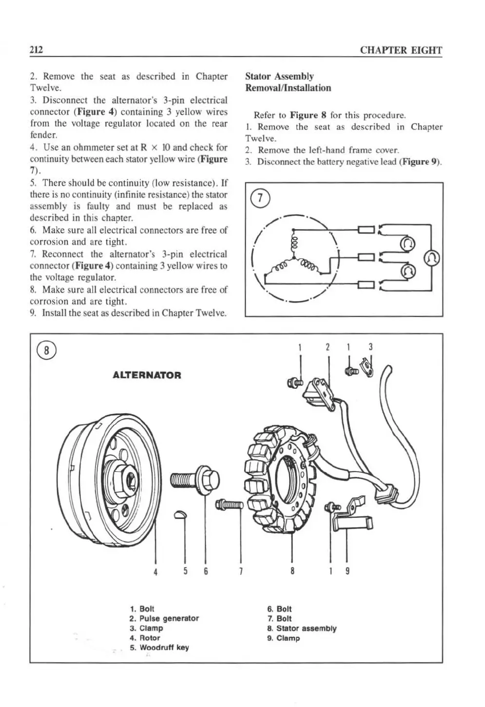
ALTERNATOR
•
5
6
1. Bolt
2. Pulse generlilor
3. Clamp
4. Rotor
5.
Woodruff
key
Stator
Assembly
Remm
'al/Installation
CHAPTER EIGHT
Refer to
Figure
8 for this procedure.
I. Remo
ve
the se
at
as described in Chapter
Twelve.
2. Remove the left-hand frame cover.
3.
Disco
nn
ec
lth
e battery negative lead (Figure 9).
8
6.
Bolt
7. Bolt
8.
SlI
l
or
assembly
9. CI.mp
 Loading...


