104
b.
Apply cutting oil
10
both the new valve guide
and the valve guide reamer.
CAUTION
Always rorale the
\'(l/~'e
guille reamer
clockwise.
If
(he
reamer is rotated
cOllfllerclockwise, damage
to
a
good
\'all,t! guide will occur.
c. ROlale the r
eamer
clockwise. Continue to
rotate the reamer and work
it
down through
the
entire length
of
the new valve guide. Apply
additional cutting oil
during
this procedure.
d.
Rotate the reamer clockwise until the reamer
has traveled
a
ll
the way through the new
va
l
ve
guide.
c. While rotating the reamer
clockwise. withdraw
the reamer from the valve guide. Remove the
reamer.
14
. If necessary. repeal Steps
1-13
for
any other
valve guides.
1
5.
Thoroughly clean the
cy
linder head and valve
guides with solvent to wash out
al1
metal particles.
Dry with compressed air.
16
. Refa
ce
the valve seats as described in this
chapter.
17
. Install the intake pipe. To prevenl a vacuum
leak, install a new
O-ring seal between the inlake
pipe and the
cy
linder head.
In
sta
ll
the intake pipes
and tighten the screws securely.
Va
h'e Seat Inspection
1.
Remove the valves as described
in
this chapter.
2. The most accurate method for checking the
valve seal is to use
Pru
ssian Blue
or
machinist's
dye. available from auto parts stores
or
machine
shops, To check the valve seal with Prussian Blue
or
machinist's dye. perform the following:
a. Thoroughly clean o
ff
all carbon deposits from
the valve face with
so
lvent
or
detergenl. then
dry
thoroughly.
b.
Spread a thin layer
of
Pru
ssian Blue
or
machinist's dye evenly on the valve face.
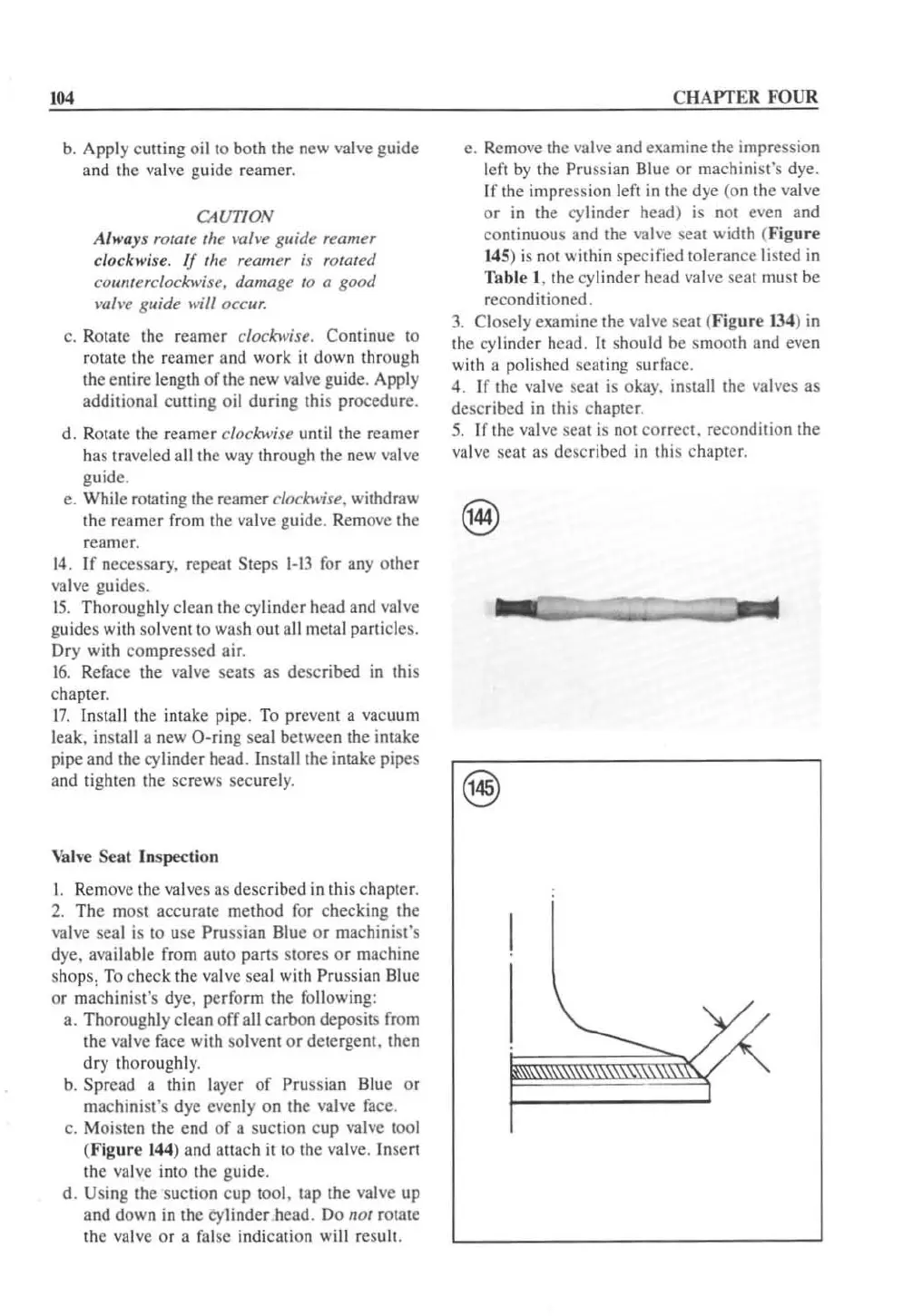
c. Moisten the end of a suction
cup
valve
1001
(F
ig
ur
e 144) and atlach
ilto
the valve.
In
se
rt
the valve inlo the guide.
d.
Using the suction cup tool. lap the
va
lve up
and down
in
the cylinder head.
Do
nol rOlate
the valve
or
a
fa
lse indication wi
ll
result.
CHAPTER FOUR
e. Remove the valve and exam inc the impression
left
by
the Pruss ian Blue
or
machinist's dye.
If
the impression left in the dye (on the valve
or
in the cylinder head) is not even and
continuous and the
valve scat width (
Figure
14
5) is
nOi
within specified tolerance listed
in
Table I . the cylinder head valve seal must be
reconditioned.
3.
Closely examine the valve seal (Fi
gure
134
)
in
the cylindcr head. It shou
ld
be smooth and even
with a polished seating surface.
4.
If
the valve scat is okay. install thc valves as
described in this chaptcr.
5.
If the valve seat
is
n
ot
correci. recondition the
va
l
ve
seat as described
in
this cha
pt
er.
 Loading...


