ELECTRICAL SYSTEM
5.
Stan the engine and let
it
id
le. then
in
crease
engine speed
to
5.000 rpm.
NOTE
I" Step 6 connect the I'oitmeler
te
st
lelllJs
to
Ihe
altemator
SW
tor side o/the
electrical connector disconnected
in
Step
4.
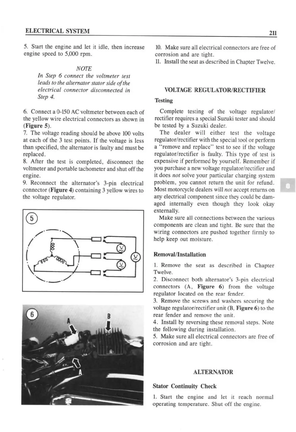
6.
Connect a 0-150
AC
vo
ltm
eter between each
of
the ye
ll
ow wire electrical connectors as shown in
(Figure 5),
7.
The
voltage reading should
be
above
100
valls
at
each
of
the 3 test poinls. If the
vo
ltage is less
than specified, the alternator
is
faulty and must
be
r
ep
laced.
8. After the test is completed. disconnect the
voltmeter a
nd
ponable tachometer and shut
off
the
eng
in
e.
9. Reconnect the alternator's 3-pin electrical
co
nn
eclQr (
Figure
4) containing 3 yellow wires to
the vohagc regulator.
2U
1
0.
Make sure a
ll
electrical connectors
are
free
of
cor
rosion and are tight.
11
.
In
sta
ll
the scat as described
in
Chapter Twelve.
VOLTA
GE REGULATOR/RECTIFIER
Testing
Complete
te
sting
of
the voltage regulator/
rectifier requires a special
Suzuki tester and should
be tested
by
a Suzuki dealer.
The
dea
l
er
will ei
ther
test the voltage
regulator/rectifier with the special tool
or
perform
a
"remove and replace" test to sec if the voltage
regulator/rectifier
is
faulty. This type
of
test is
expensive
if
performed
by
yourself. Remember
if
you
pu rcha
se
a new voltage regulator/rectifier and
it does
"at
solve your particular charging system
problem. you cannot return the unit for refund.
Most motorcycle dealers will
"or accept returns on
any electrical component since they could be dam-
aged
internally even though they look okay
externally.
Make sure all connections between the
va
ri
ous
components arc clean and tight. Be sure that the
wiring connectors
are
pushed together firmly to
help keep out moisture.
RemO\-lI
l/
l n
sta
Uation
I.
Remove the seat as de
sc
ribed
in
Chapter
Twel
ve.
2. Disconnect both alternator's 3-pin electrical
co
nn
ectors (A.
Figure
6) from the voltage
regulator located on the rear fender.
3.
Remove the screws and washers securing the
voltage regulator/rectifier unit (B. Fig
ur
e 6) to the
rear fender and remove the unit.
4. Insta
ll
by
reversing these removal steps. Note
the
fo
ll
owing during installation.
5.
Make sure all electrical connectors are free
of
corrosion and are tight.
ALTERNATOR
Stator
Co
ntinuity C
hec:k
I. Start the engine and let
it
reach normlll
operating temperature. Shut
off
the engine.
 Loading...


