244
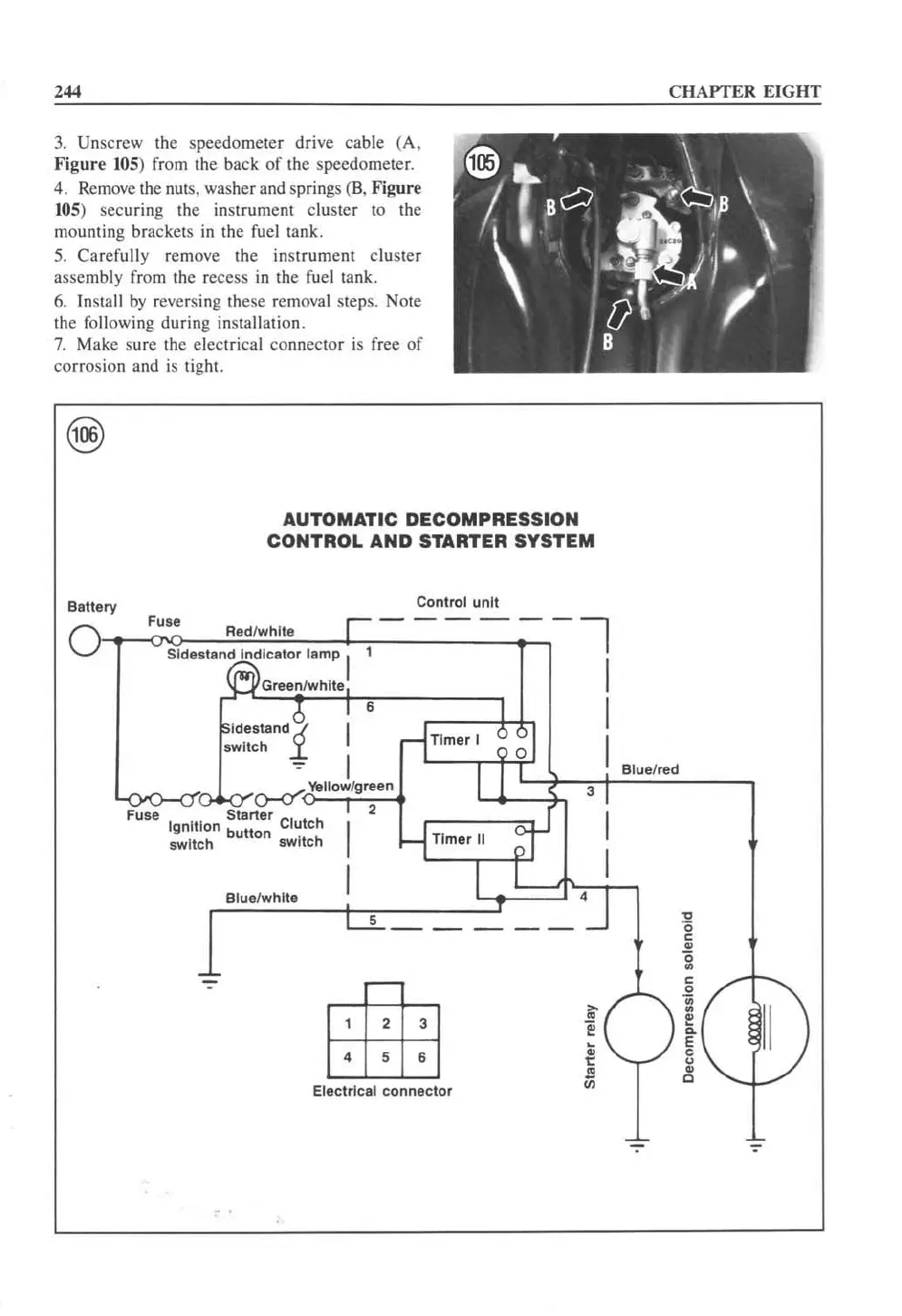
3.
Unscrew the speedometer drive cable (A,
Figure
105
) from the back
of
the speedomete
r.
4. Rem
ove
the nms. washer a
nd
springs (S. Figure
105
) securing the instrument cluster
to
the
mounting brackets
in
the [uel tank.
5.
Carefully remove the instrume
nt
cluster
assembly from
th
e recess
in
the
fue
l tank.
6.
Install by reversing these removal steps. Note
the following during installation.
7.
Make su re the electrical connector
is
free
of
corrosion
an
d
is
tight.
Battery
AUTOMATIC
DECOMPRESSION
CONTROL
AND
STARTER
SYSTEM
Control
unit
}-,-
__
Fo"~·
g
·CcC-c"7·7de
l
"W~hc"!·~coc~r--,-
____
~~_-_-
__
===-.~~,--
~
sldestan~lc8tor
lamp
I '
~Green
f
whlte
I
I
Idestand
~
switch
.r.
; 6
I
rlTlmer
I 0
~
I
I
I
~
Yellow/green
I
3 I
'-<F"~.{.)-Cf
N
O<~S;'Ctr'_8rter
~
2
'gnltion
b
Clutch
I
utton
switch switch
-1
Tim"
II
~
I
I I I
Blue/white
I
L..L
_____
'J
~
~
Electrical
connector
CHAPTER EIGHT
Blue/red
~
..
<
~
•
<
~
II
) I
c
u
•
0
;-
 Loading...


