242
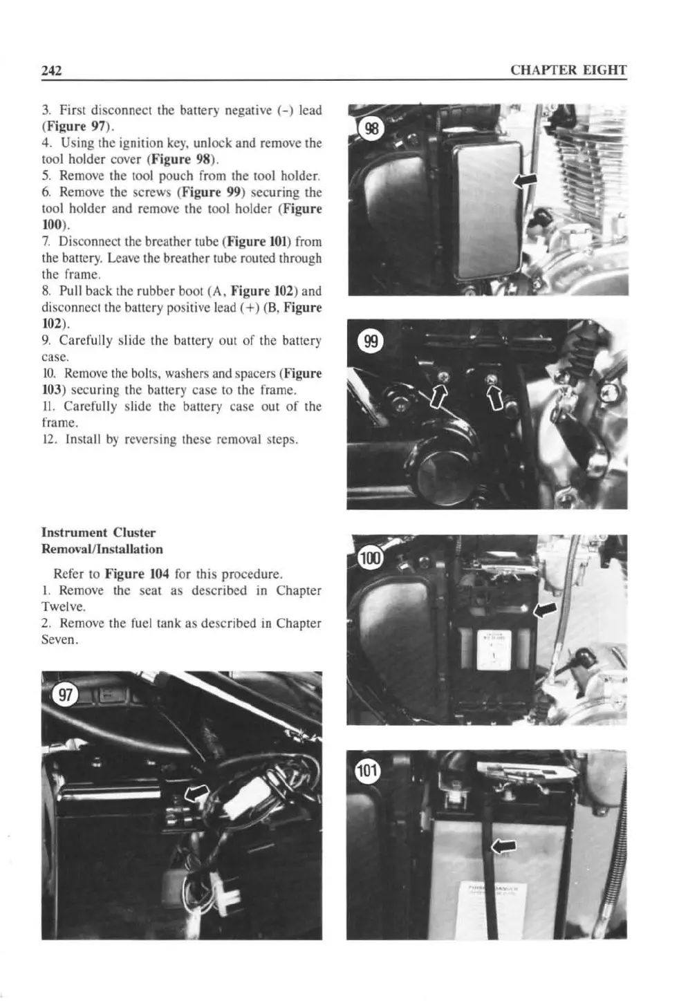
3.
First disconnect the battery negalive
(-)
lead
(Figure 97).
4. Using the ignition
key.
unlock and remove the
tool holder cover (
Figur
e 98).
5.
Remove the too\ pouch from Ihe
1001
holder
.
6.
Re
mo
ve
th
e screws (Fig
ur
e
99
) securing the
tool holder and remove the
1001
holder (Figure
100).
7.
Disco
nnccllhc
breather tube
(F
ig
ur
e
101
) fr
om
the battery. Leave the brcalhcr lube routed through
the frame.
8. Pu
ll
back the r
ubber
boot (A. Figu
re
102
) and
disconnect the battery positive lead
(+)
(
B.
Figure
102
).
9.
Carefully slide the battery out
of
the battery
casco
1
0.
Remove the bolts. washers a
nd
spacers (
Figure
103
) securing the battery
case
10
the frame.
II
. Carefu
ll
y slide the
bancry
ca
se
OUI
of
the
frame.
12
. Install
by
reversing the
se
removal step
s.
Ins
trum
e
nt
Cluster
Removal/Installation
Refer to
Figur
e 104 for this procedure.
\. Remove the seat as de
sc
ri
bed
in
Chapter
Twelve.
2. Remove the fue l tank as described
in
Chapter
Seven.
CHAPTER
EIGHT
 Loading...


