250
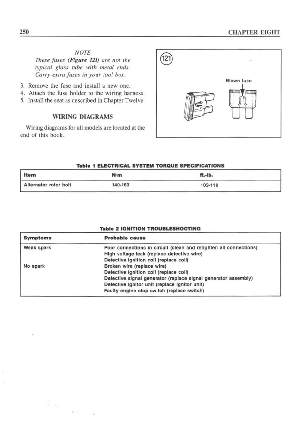
NOTE
These fuses (Figure
121
) are not
th
e
opical
glass tube with metal ends.
Carr), extra fuses in
yo
ur
1001
box.
3.
Remove the
fu
se and
in
stall a new o
ne
.
4. Attach the
fu
se holder to the wiring harness.
5.
In
sta
ll
th
e seat
as
described
in
Chapter Twelv
e.
WIRING
DIAGRAMS
Wiring diagrams for all models are located
at
the
e
nd
of this book.
'bbl.
1
ELECTRICAL
SYSTEM
TORQUE
SPECIFICATIONS
Item
ft
.. lb.
Alternator
rotor
boll
140·160
103·118
,..ble
2 IGNITION
TROUBLESHOOTING
Symptoms
CHAPTER
EIGHT
Blown fuse
m
Wesk spark Poor
connections
In
circuit
(clean and retighten all
connections)
High voltage
leak
(replace
defeclive
wire)
No spark
Defe<:tive
Ignition
coil (replace
coli)
Broken wire (replace wire)
Defective
Ignilion
coil
(replace
coli)
Defective algna' generator (replace signal generator assembly)
Defective I
gnitor
unit (replace Ignitor unit)
Fau
lty
engine atop switch (replace switch)
 Loading...


