3: Installation/Configuration
Make the following optional connections:
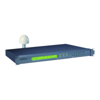
• ANTENNA: GPS receiver antenna connector with GPS antenna cable.
Warning: Use a 12-volt capable GPS antenna.
• NET: network port with the Cat-5 network cable (supplied) to an Ethernet network.
(Needed to manage the XL-GPS remotely by network, or optionally to distribute NTP
time information)
• SERIAL I/O: with RS-232 null modem cable (supplied) to the serial port on a PC.
• For J1, J2, J3, and any other option cards: See also:
• “F110 – J1 Input (Time Code, TIET)” on page128
• “F111 – J2 Output (Rate, PPO)” on page133
• “F113 – J3 Input (Freq Meas)” on page138
Connecting the Power Supply
Connect the Power Supply to a power source. Upon receiving power, the XL-GPS goes
through its startup sequence; displaying “Booting”, Loading”, and then “Starting”. After
approximately 40 seconds, the XL-GPS displays the clock status, and user interfaces (front
panel/command line) become available.
See "Grounding" on page 34
CAUTION VAC power
l The VAC Power Supply specification reflects the overall Power Supply ratings. For
UL and CE compliance the Power Supply must only be operated at 90 – 264 VAC,
120 – 370 VDC, 47– 63 Hz.
l The XL-GPS should only be plugged into a grounded receptacle.
AVERTISSEMENT:
l Les spécifications d'approvisionnement de courant alternatif ci-dessus reflètent les
estimations globales d'alimentation d'énergie. Pour la conformité d'UL et de CE l'al-
Page 28 of 221 .................................098-00116-000 Rev. A
 Loading...