EasyManuals Logo
Home>SYNAPTICON>Servo Drives>SOMANET Node 400

SYNAPTICON SOMANET Node 400 User Manual

Default Icon
887 pages
To Next Page IconTo Next Page
To Previous Page IconTo Previous Page
Page #265 background imageLoading...
Page #265 background image
Safe brake output (SBC)
Number of digital outputs 2 (dual-channel safety output for one brake
system)
Max. output voltage Servo drive main power supply (48 VDC)
Min. output voltage 0 V
Max. current. 1 A
Max. peak current. 4 A
Note
This PWM controlled brake is configured by the same object as the regular brake.
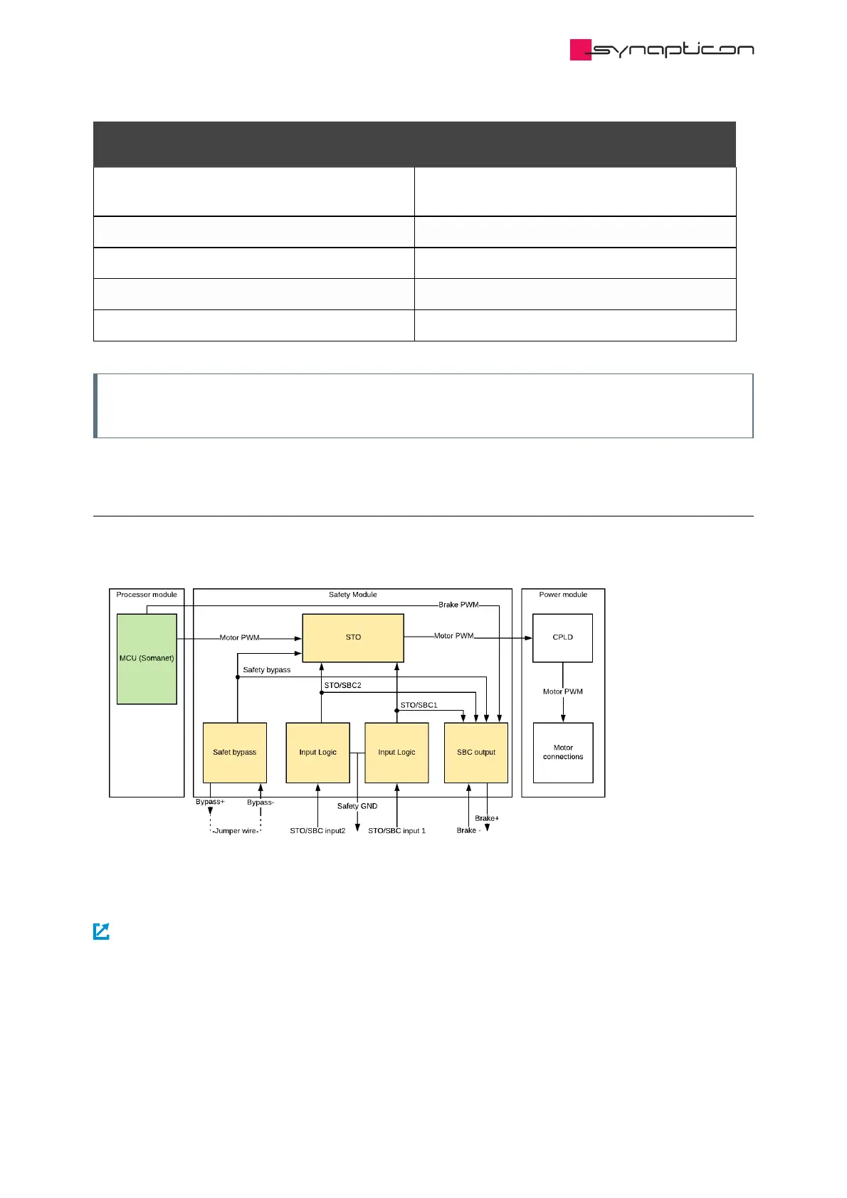
1.3.2.6.2.3 Block diagram
Simplified block diagram of SOMANET Node Safety:
For details of the connectors please refer to:
Safety connectors
Synapticon Documentation
© 2021 Synapticon GmbH | Daimlerstraße 26 | D-71101 Schönaich Documentation v 4.11.0 | Built 2021-07-23 265/887

Table of Contents

Other manuals for SYNAPTICON SOMANET Node 400

Questions and Answers:

Question and Answer IconNeed help?

Do you have a question about the SYNAPTICON SOMANET Node 400 and is the answer not in the manual?

SYNAPTICON SOMANET Node 400 Specifications

General IconGeneral
BrandSYNAPTICON
ModelSOMANET Node 400
CategoryServo Drives
LanguageEnglish

Related product manuals