3.1.3.3 Brake configuration
In some cases, the motor is equipped with a mechanical brake which can be released by applying electrical
voltage to the brake’s terminals.
A configurable voltage is applied to the positive terminal of motor brake (It is assumed that the negative
terminal of the brake is connected to Ground).
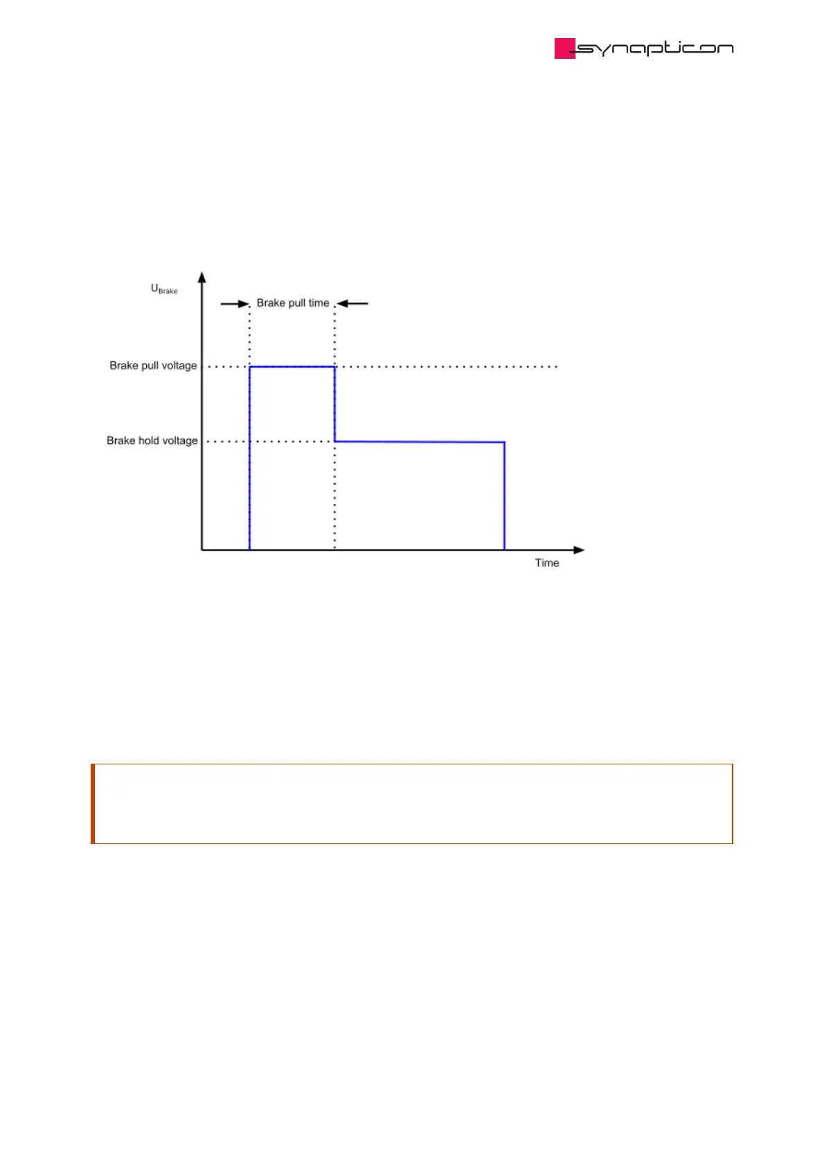
When the motion system has entered operation enabled, the specified “Brake pull voltage” will be automatically
applied for a configurable amount of time designated as “Brake pull time”. After this time period, the second
voltage level “Brake hold voltage” will be applied to the brake terminals permanently. The brake hold voltage
can be set to a lower value to save energy.
Attention
Don’t set the hold voltage too low or you risk entering a marginally stable situation where any jerk can
engage the brake.
Once the motion system leaves the state “operation enabled” the voltage is automatically dropped to Ground
after the designated time “Brake engage delay” and the brake is mechanically activated.
 Loading...

