Attention
Applying more voltage to the brake than required will increase the brake temperature and damage the
brake.
Danger
If the brake overheats while it’s released, the internal deformations might block the brake in the release
state!
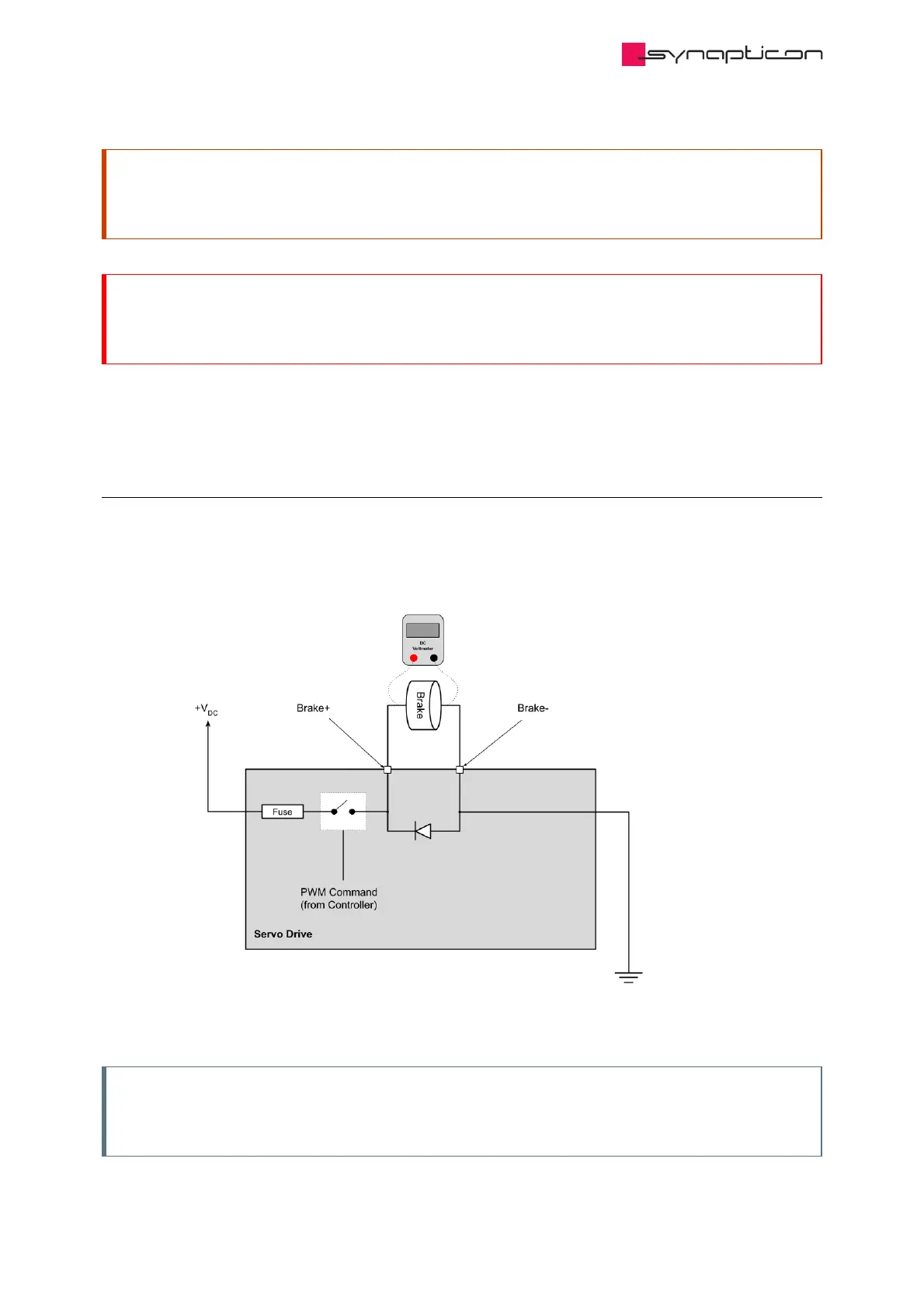
Measuring the brake current can be done with a DC ampere meter and measuring the brake DC voltage is
possible with a common DC voltmeter.
4.1.4.1 Non-safety brake output
The image below shows a non-safety brake circuit. Measuring the non-safety brake voltage can be done by
connecting the voltmeter probe to the brake output (phase D on SOMANET Node) and ground.
Note
The brake or a similar electrical load has to be connected to the brake outputs when measuring the
output voltage. Without a load, the multimeter will show an incorrect input DC voltage!
 Loading...

