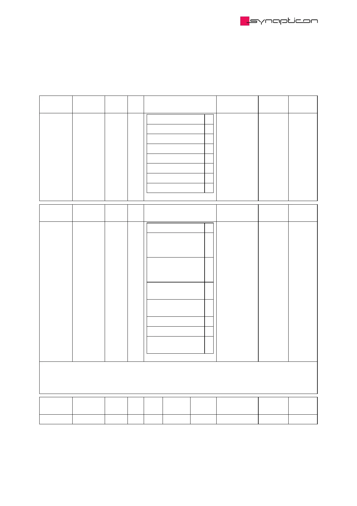
3.1.9.1.74 0x2205 Incremental encoder 1
Configuration parameter for first incremental encoder
Name Index:Sub Type Bit
Size
Options Unit Access PDO
Mapping
Type 0x2205:1 USINT 8
HALL 1
Incremental 2
A-Format 3
BISS 4
REM 16MT 6
SSI 7
iC-MD 8
iC-NQC 9
readonly
(default)
Name Index:Sub Type Bit
Size
Options Unit Access PDO
Mapping
Function 0x2205:2 USINT 8
Disabled 0
Commutation &
Motion Control
Feedback
1
Commutation &
Monitoring
(#0x230A, #0x230B)
2
Motion Control
Feedback only
3
Monitoring only
(#0x230A, #0x230B)
4
Commutation only 5
Position 6
Commutation &
Velocity
7
readwrite
Determines encoder function/purpose. The encoder can be configured for commutation, motion control
feedback and monitoring. In monitoring mode, the position and velocity information will be displayed in
objects #0x230A & #0x230B. There is an option to configure two motion sensors, one sensor as a motion
position sensor, while the other sensor should have commutation and velocity function.
Name Index:Sub Type Bit
Size
Min
Data
Max
Data
Default
Data
Unit Access PDO
Mapping
Resolution 0x2205:3 UDINT 32 1 1 Inc/Revolution readwrite
 Loading...

