3.1.8.2.1.1 Cyclic Synchronous Torque Mode
In this mode, the trajectory generator is located in the control device, not in the servo drive. In a cyclic
synchronous manner, it provides a target torque to the drive device, which performs torque control.
Optionally, an additive torque value can be provided by the control system in order to allow two instances to
set up the torque.
The cyclic synchronous torque mode covers the following sub-functions:
demand value input;
torque capture;
torque control function with appropriate input and output signals;
limitation of torque demand.
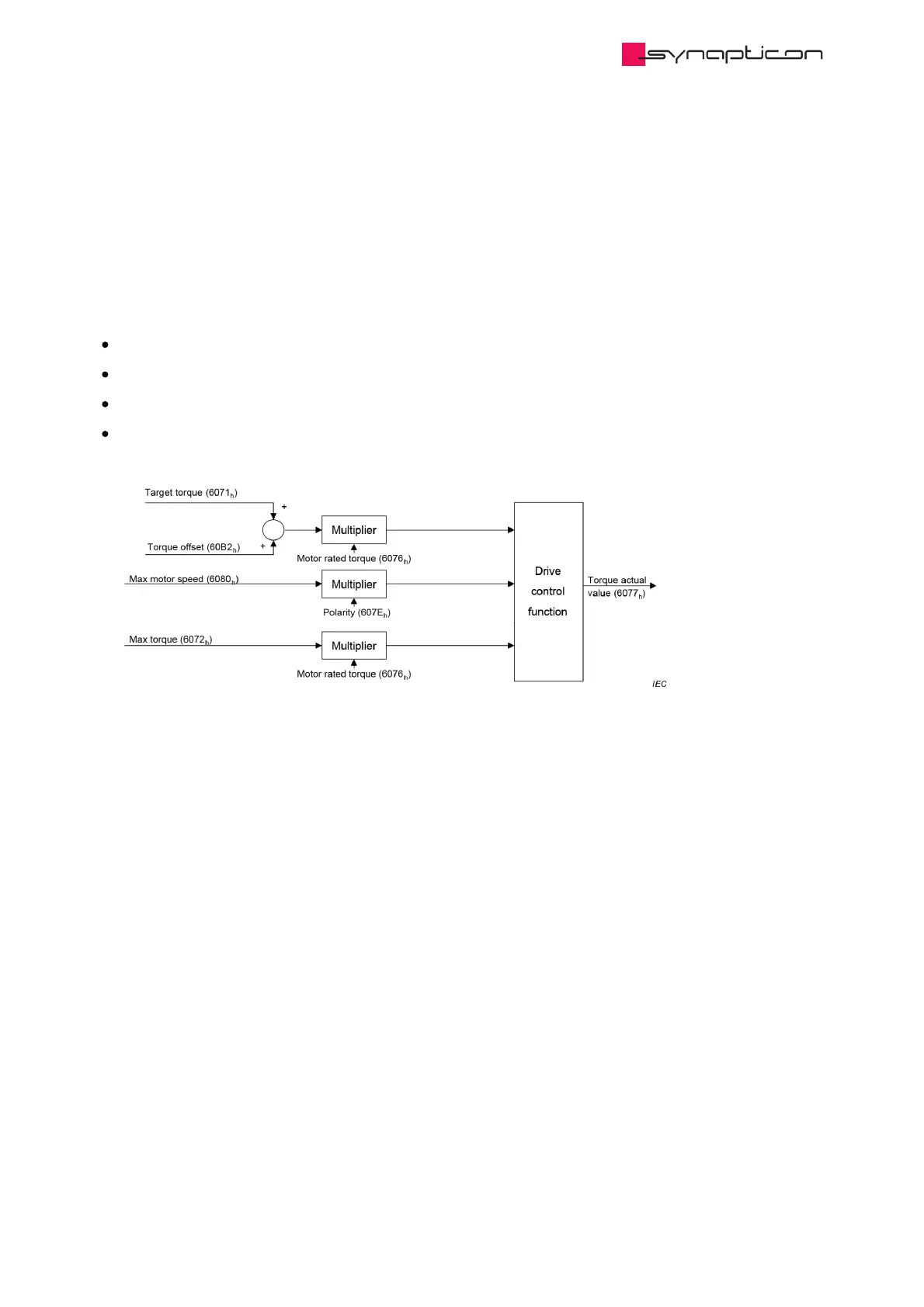
The figure above shows the inputs and outputs of the torque control function. The input (from the control
function point of view) are the target torque and optionally a torque offset which is added to the target torque
to allow two instances to set up the torque.
The torque can be limited in object 0x6072 Max torque.
The torque actual value is used as mandatory output to the control device.
 Loading...

