EasyManuals Logo

SYNAPTICON SOMANET Node 400 User Manual

Default Icon
887 pages
To Next Page IconTo Next Page
To Previous Page IconTo Previous Page
Page #843 background imageLoading...
Page #843 background image
4.1.4.2 Safety brake output
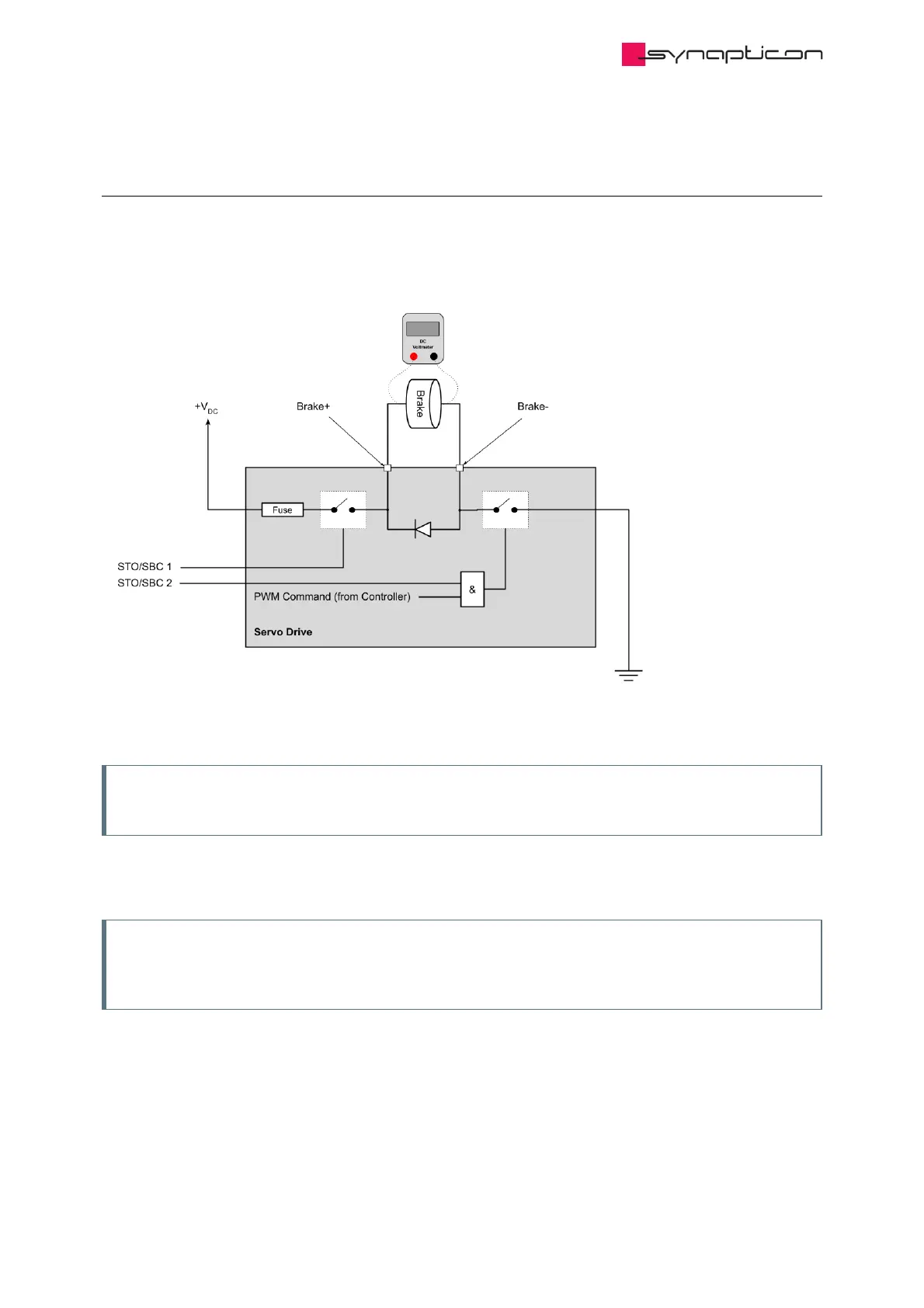
The image below shows the safety brake circuit. The PWM signal is connected to a switch that is connected to
Ground (GND). So for controlling the voltage level, it is generating a PWM signal on the GND side.
Note
The PWM signal is generated on the Brake- side.
For measuring the safety brake output voltage, B+ and B- must be connected to the voltmeter. Measuring the
voltage between B+ and GND or B- and +V will result in a wrong value.
Note
The brake or a similar electrical load has to be connected to the brake outputs when measuring the
output voltage. Without a load, the multimeter will show an incorrect input DC voltage.
In
Synapticon Documentation
© 2021 Synapticon GmbH | Daimlerstraße 26 | D-71101 Schönaich Documentation v 4.11.0 | Built 2021-07-23 843/887

Table of Contents

Other manuals for SYNAPTICON SOMANET Node 400

Questions and Answers:

Question and Answer IconNeed help?

Do you have a question about the SYNAPTICON SOMANET Node 400 and is the answer not in the manual?

SYNAPTICON SOMANET Node 400 Specifications

General IconGeneral
BrandSYNAPTICON
ModelSOMANET Node 400
CategoryServo Drives
LanguageEnglish

Related product manuals