EasyManuals Logo

SYNAPTICON SOMANET Node 400 User Manual

Default Icon
887 pages
To Next Page IconTo Next Page
To Previous Page IconTo Previous Page
Page #851 background imageLoading...
Page #851 background image
4.1.6.2.1 General structure of the Statusword
The basic bits (0-7) are identical in each mode.
The red marked bits 9 and 14-15 are not supported (N/A)
The yellow marked bits have a specific functions which depends on the mode the drive is currently in. See
the documentation of the specific mode for details.
1515
1414
1313
1212
1111
1010
99
88
77
66
55
44
33
22
11
00
ms
oms
oms
ila
tr
rm
ms
w
sod
qs
ve
f
oe
so
rtso
N/A
operation mode specific bits
N/A
basic
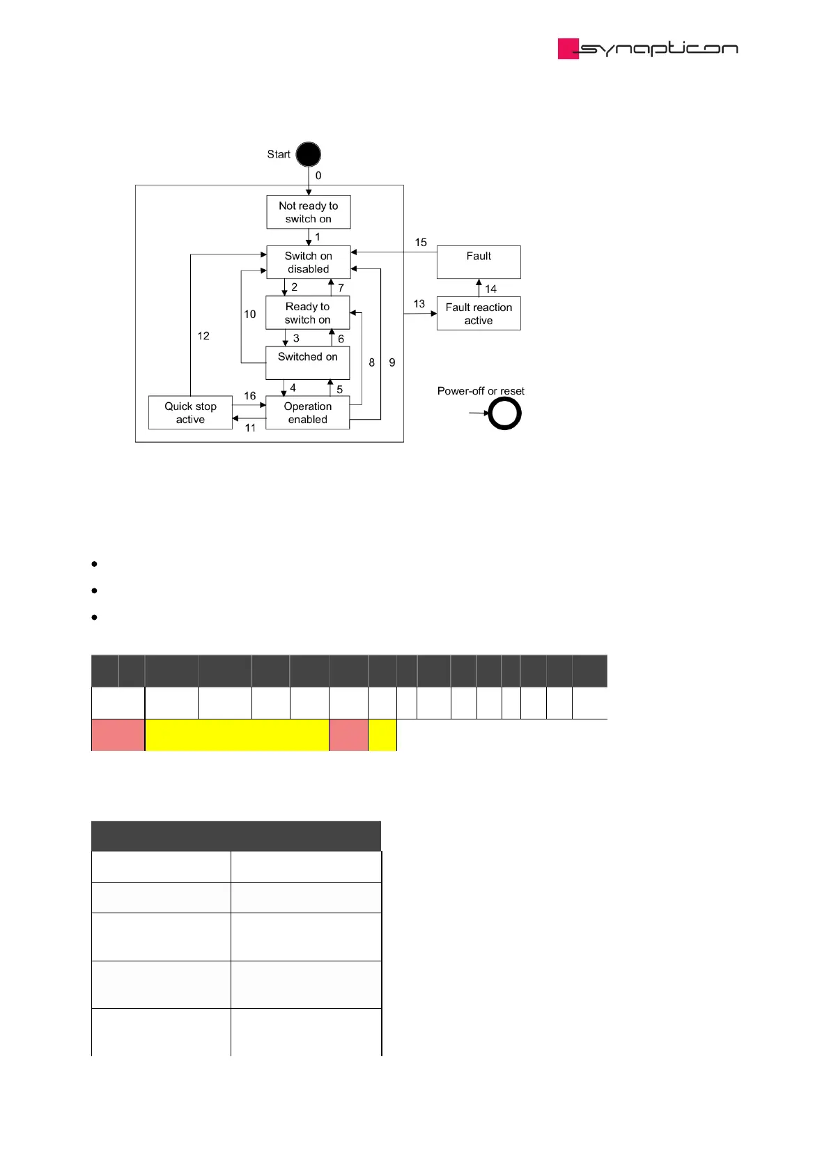
The basic bits of the statusword indicate in which state the drive is:
State coding
Statusword FSA state
xxxx xxxx x0xx 0000b Not ready to switch on
xxxx xxxx x1xx 0000b Switch on disabled
xxxx xxxx x01x
0001b
Ready to switch on
xxxx xxxx x01x
0011b
Switched on
xxxx xxxx x01x
0111b
Operation enabled
Synapticon Documentation
© 2021 Synapticon GmbH | Daimlerstraße 26 | D-71101 Schönaich Documentation v 4.11.0 | Built 2021-07-23 851/887

Table of Contents

Other manuals for SYNAPTICON SOMANET Node 400

Questions and Answers:

Question and Answer IconNeed help?

Do you have a question about the SYNAPTICON SOMANET Node 400 and is the answer not in the manual?

SYNAPTICON SOMANET Node 400 Specifications

General IconGeneral
BrandSYNAPTICON
ModelSOMANET Node 400
CategoryServo Drives
LanguageEnglish

Related product manuals