EasyManuals Logo

SYNAPTICON SOMANET Node 400 User Manual

Default Icon
887 pages
To Next Page IconTo Next Page
To Previous Page IconTo Previous Page
Page #854 background imageLoading...
Page #854 background image
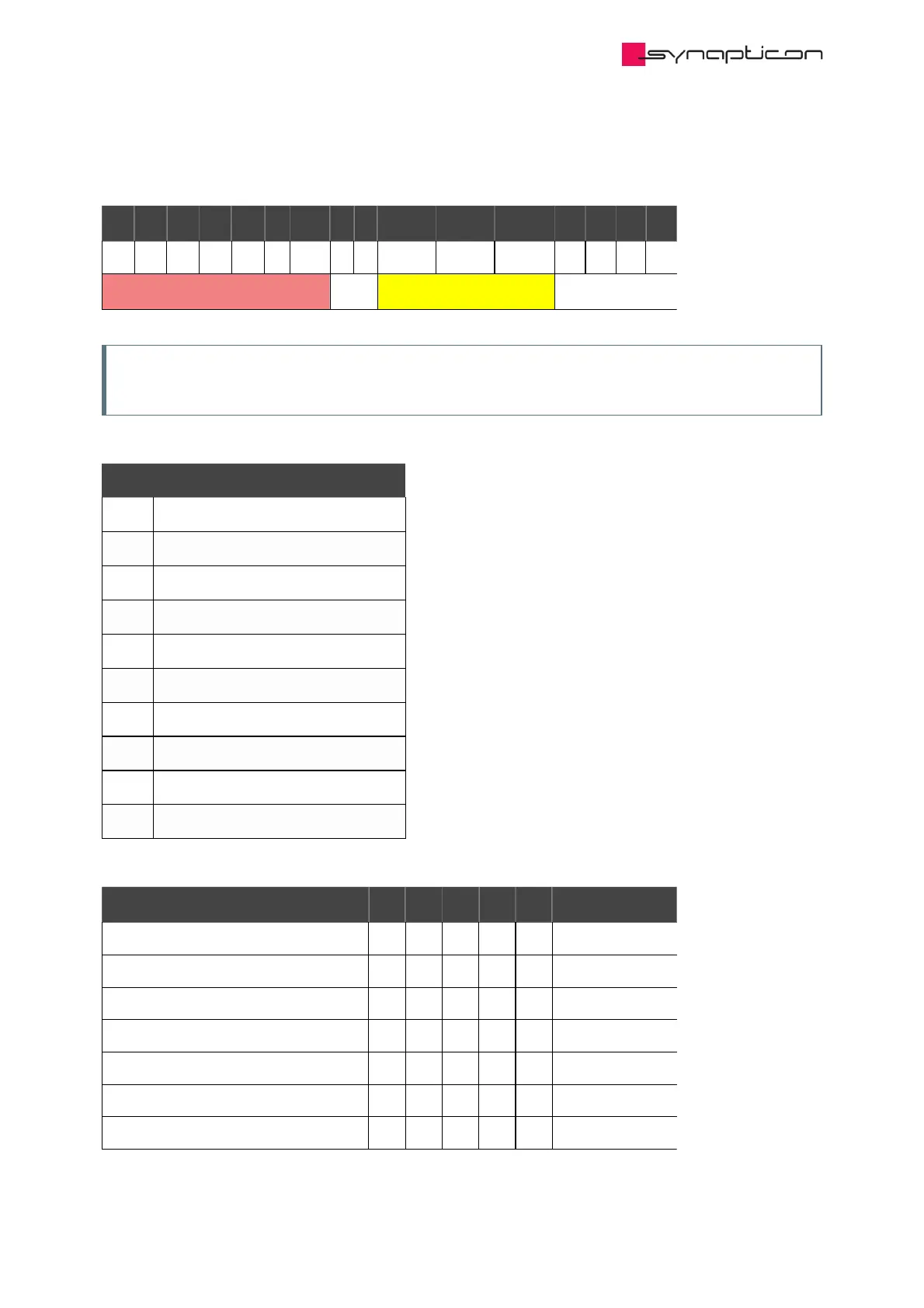
4.1.6.2.4 General structure of the Controlword
1515
1414
1313
1212
1111
1010
99
88
77
66
55
44
33
22
11
00
ms
ms
ms
ms
ms
r
oms
h
fr
oms
oms
oms
eo
qs
ev
so
N/A
basic
operation mode specific bits
basic
Note
bits 9,10,11,12,13,14 and 15 are not used.
Legend:
Abbr. Meaning
so switched on
ev enable voltage
qs quick stop
eo enable operation
oms operation mode specific
fr fault reset
h halt
oms operation mode specific
r reserved
ms manufacturer specific
State Coding
CommandCommand
b7b7
b3b3
b2b2
b1b1
b0b0
TransitionsTransitions
Shutdown
0
x
1
1
0
2,6,8
Switch on
0
0
1
1
1
3
Switch on + enable operation
0
1
1
1
1
3+4 (NOTE)
Disable voltage
0
x
x
0
x
7,9,10,12
quick stop
0
x
0
1
x
7,10,11
disable operation
0
0
1
1
1
5
enable operation
0
1
1
1
1
4,16
Synapticon Documentation
© 2021 Synapticon GmbH | Daimlerstraße 26 | D-71101 Schönaich Documentation v 4.11.0 | Built 2021-07-23 854/887

Table of Contents

Other manuals for SYNAPTICON SOMANET Node 400

Questions and Answers:

Question and Answer IconNeed help?

Do you have a question about the SYNAPTICON SOMANET Node 400 and is the answer not in the manual?

SYNAPTICON SOMANET Node 400 Specifications

General IconGeneral
BrandSYNAPTICON
ModelSOMANET Node 400
CategoryServo Drives
LanguageEnglish

Related product manuals