EasyManuals Logo

SYNAPTICON SOMANET Node 400 User Manual

Default Icon
887 pages
To Next Page IconTo Next Page
To Previous Page IconTo Previous Page
Page #841 background imageLoading...
Page #841 background image
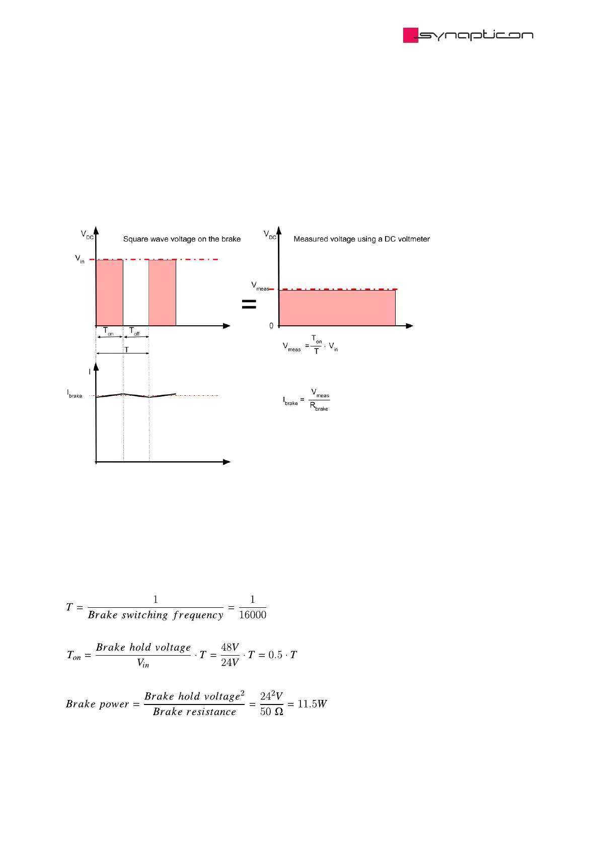
4.1.4 Measuring the brake output voltage
The brake voltage is a square wave signal 16 kHz, 32 kHz or 64 kHz (configurable in subitem 2004:11). A PWM
method is used for applying the appropriate voltage to the brake output.
The brake output voltage does not have a negative component. It is connected to an inductor which results in
a constant current.
Example
V (Input DC voltage) = 48 V
Brake switching frequency = 16 KHz
Brake hold voltage = 24 V
Brake resistance = 50 Ω
in DC
Synapticon Documentation
© 2021 Synapticon GmbH | Daimlerstraße 26 | D-71101 Schönaich Documentation v 4.11.0 | Built 2021-07-23 841/887

Table of Contents

Other manuals for SYNAPTICON SOMANET Node 400

Questions and Answers:

Question and Answer IconNeed help?

Do you have a question about the SYNAPTICON SOMANET Node 400 and is the answer not in the manual?

SYNAPTICON SOMANET Node 400 Specifications

General IconGeneral
BrandSYNAPTICON
ModelSOMANET Node 400
CategoryServo Drives
LanguageEnglish

Related product manuals