EasyManuals Logo

SYNAPTICON SOMANET Node 400 User Manual

Default Icon
887 pages
To Next Page IconTo Next Page
To Previous Page IconTo Previous Page
Page #417 background imageLoading...
Page #417 background image
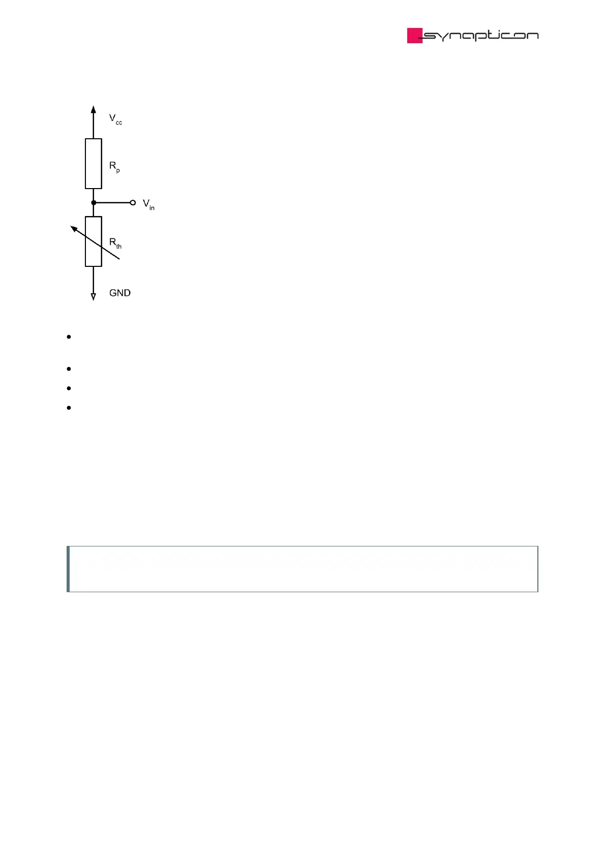
V represents the value of voltage at which the ADC is connected to, causing the ADC to count an output of
4095.
R represents the pull-up resistor.
R is a resistive sensor, e.g. a thermistor or strain gauge.
V is the voltage that is connected to the selected analog input.
The cut-off frequency of the low-pass filter (0x2038:10) for the analog input can also be tweaked to further
fine-tune the unscaled analog input before feeding it to the scaling algorithm.
cc
p
th
in
3.1.4.1.4.2.3 Thresholds
Upper and lower level thresholds can be configured in subitems 0x2038:11 and 0x2038:12. When these
thresholds are breached an error is triggered in the Error report object.
Note
When the value approaches 95% of the defined thresholds, a warning is triggered.
Synapticon Documentation
© 2021 Synapticon GmbH | Daimlerstraße 26 | D-71101 Schönaich Documentation v 4.11.0 | Built 2021-07-23 417/887

Table of Contents

Other manuals for SYNAPTICON SOMANET Node 400

Questions and Answers:

Question and Answer IconNeed help?

Do you have a question about the SYNAPTICON SOMANET Node 400 and is the answer not in the manual?

SYNAPTICON SOMANET Node 400 Specifications

General IconGeneral
BrandSYNAPTICON
ModelSOMANET Node 400
CategoryServo Drives
LanguageEnglish

Related product manuals