1730–Series Theory of Operation
4–16
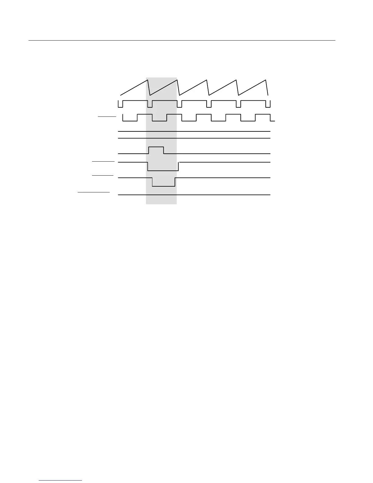
COMP SYNC
H SYNC
LIN SEL EN
LISEL
LIN STRB
PIXSTRB
H LIN SEL EN
2H SWEEP
(LOW)
(HIGH)
DISPLAYED
LINE
Figure 4-7: Relative line select timing elements for the 1-line display.
Sweep Generators and Horiz Output
Diagram 4
U552B (Line Rate Sweep Generator) and U552A (Field Rate Sweep Generator)
are integrators, one of which is disabled while the other is running. The selec–
tion is controlled by the H and V Trigger signals from the Sync Generators (Dia–
gram 3) and the LIN/FLD control line from the Microcontroller. When a trigger
arrives, for the selected sweep, the D-type flip-flop (U541A or B) Clear is high
and Preset is low, to set Q high and turn on Q451 or Q450, which discharges the
integrating capacitor (C448 or C453). See Figure 4-8. The Q output of U541A
or B going high also starts a one-shot (U741A or B) which pulls the flip-flop
Preset low which assures at least 2 ms (line-sweep one-shot time constant) of
discharge (retrace) time. Field sweep one-shot time constant is 2 ms. At the end
of the time constant Preset goes high and Clear goes low causing the flip-flop Q
output to go low and turn off Q451 or Q450 to start charging the integrating
capacitor.
Current source for the integrators is through R654. When a one line or field
sweep (including RGB parade) is selected, pin 3 of U735A is pulled low and
effectively shorts out R654 to provide more current for a faster sweep. Q750
provides a compensation for 50 Hz sweep by taking away a small amount of
current when operating with 625/50 Hz sweep rates.
Sweep Generator

 Loading...


