1730–Series Theory of Operation
4–17
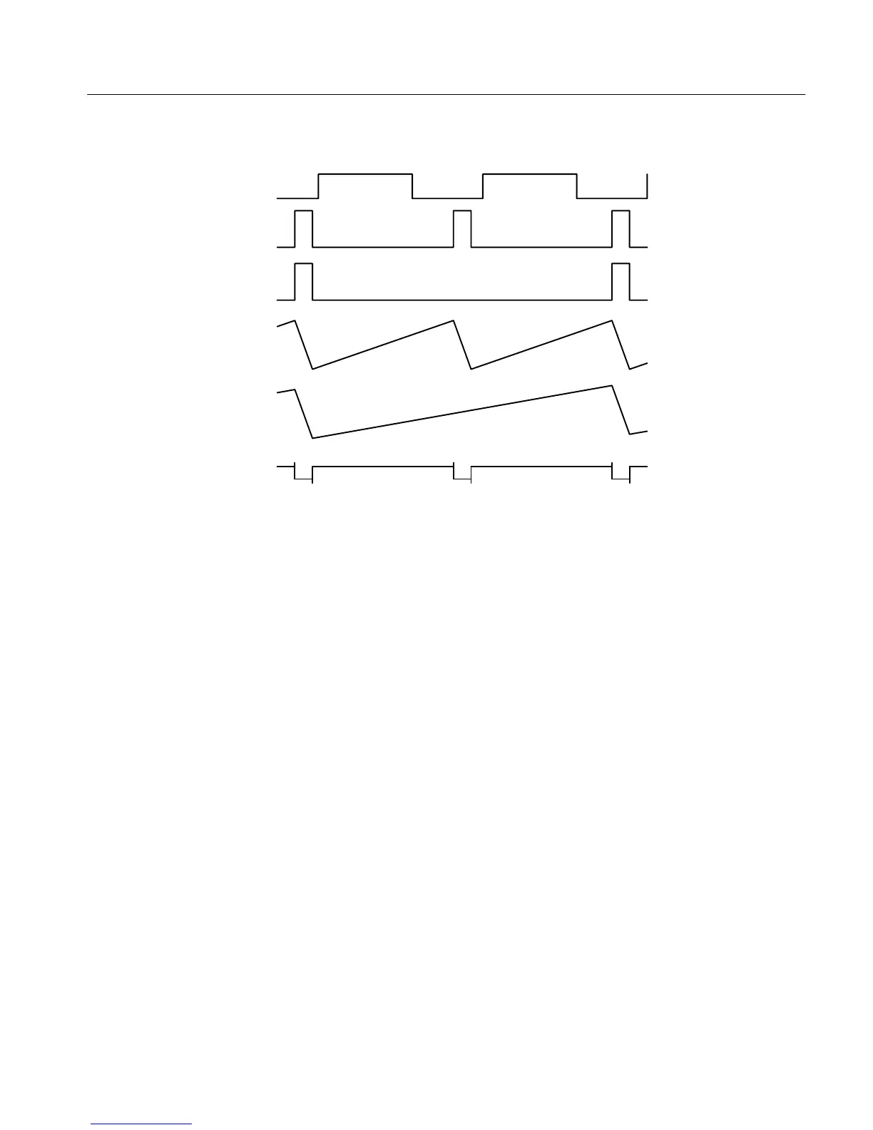
U541 PIN 3
H TRIGGER
U541 PIN 5 (Q)
1-LINE SWEEP
WITH SYNC
U541 PIN 5 (Q)
2-LINE SWEEP
WITH SYNC
U552 PIN 6
1-LINE SWEEP
U552 PIN 6
2-LINE SWEEP
U741 PIN 6
Figure 4-8: Timing signals for 1-line and 2-line sweep.
If there is no H or V Trigger, the output of the running Sweep Generator is self
retriggered. When the ramp amplitude reaches about 3/4 of its maximum
amplitude U445B trips and sets the flip-flop Preset high to turn on Q451 or
Q450 to start retrace. Just before retrace begins U445A also trips and pulls the
flip-flop Clear high to lock out the trigger signal.
The Microcontroller-generated 2H SWP PH retriggers the Line Rate Sweep
Generator by turning on Q451 (which discharges the integrator capacitor, C453)
to synchronize the sweep for Line Select or when dual filtering or input
switching is selected.
The output of either one-shot, or LINSEL BLNK, is gated through U334B to
become the blanking enable, which ensures that the CRT will be blanked during
retrace and unblanked during the portion of active sweep that is to be displayed.
An operational amplifier consisting of U564C and D and Q566 positions and
magnifies the sweep signal. R557 and R558 are the central elements of the
feedback resistor network. The value of the network is altered by R552 (1 ms
Cal) and R553 (0.2 ms Cal) when magnified sweep rates are selected. The
junction of input resistance (R559) and the feedback resistance network (R557
and R558) is the amplifier input summing junction.
Horizontal positioning voltage is input to an operational amplifier, U655B,
which drives the Magnifier Amplifier summing point (along with the RGB
Magnifier Amplifier

 Loading...


