1730–Series Maintenance
6–6
exploded view drawing comprise Section 10 of this manual. Standard Accesso-
ries, which are also included in the parts list, are also in the exploded view
drawing.
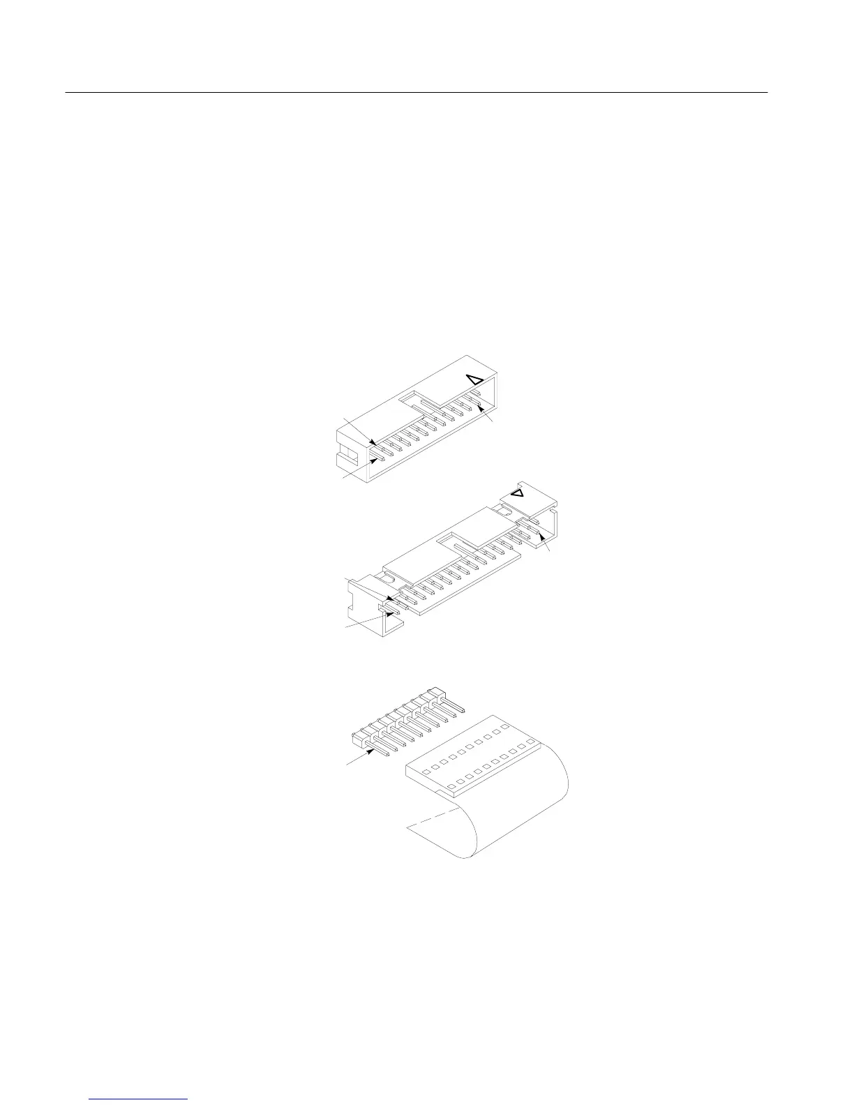
Signals and power supply voltages are passed through the instrument with a
system of interconnecting cables. The connector holders, on these cables, have
numbers that identify terminal connectors; numerals are used from pin 2 up. A
triangular key symbol is used to identify pin 1 on the circuit board to assist in
aligning connector with correct square pins. Fig. 6-2 shows the numbering
scheme (and the triangular marking) on the etched circuit board.
Circuit board mounted pins
PIN 1
Moveable 10–pin plug
Square pin connector on
power supply circuit board
PIN 1
PIN 1
ROW A
ROW B
ROW B
ROW A
24 and 34 pin circuit
board connectors on
Main circuit board
Figure 6-2: Multiple pin connectors used in the 1730–Series Waveform
Monitor.
Major Assembly
Interconnection
 Loading...


