1730–Series Operating Instructions
2–16
(PAL) and checking that the maximum excursion of color burst is at approxi-
mately the 100 IRE or 1 V graticule line.)
Push the button in and hold it until both the VAR and X5 indicators are lit.
Rotate the GAIN control and look for a greater than 5X amplitude display at one
extreme and a nearly normal amplitude display at the other extreme.
Push the GAIN button once and notice that the display amplitude returns to 1 V
Full Scale.
10. Filter Selection
The FILTER button selects the frequency response characteristic for the
displayed signal. The FLAT response is used for normal applications. Fig-
ure 2-4 shows the color bar signal with the FLAT response.
0V
1.2
1.0
1.1
0.9
0.8
0.7
0.6
0.5
0.4
0.2
0.1
0
PAL
–0.3
+0.7
Tek 2% & 4% K FACTOR
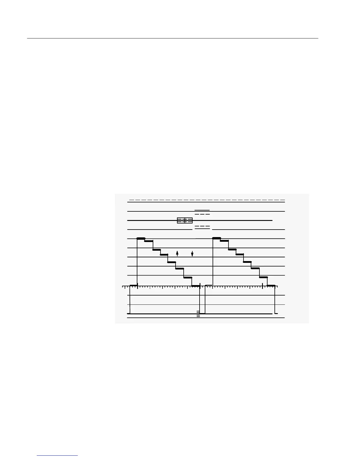
Figure 2-8: Two–line display of color bar signal with LOW PASS filter on.
Press and hold the FILTER button to get the front–panel LPASS indicator to
light. This provides the low pass frequency response; the chrominance
component of the signal has been removed. See Figure 2-8.

 Loading...


