1730–Series Operating Instructions
2–12
0V
1.2
1.0
1.1
0.9
0.8
0.7
0.6
0.5
0.4
0.2
0.1
0
PAL
–0.3
+0.7
Tek 2% & 4% K FACTOR
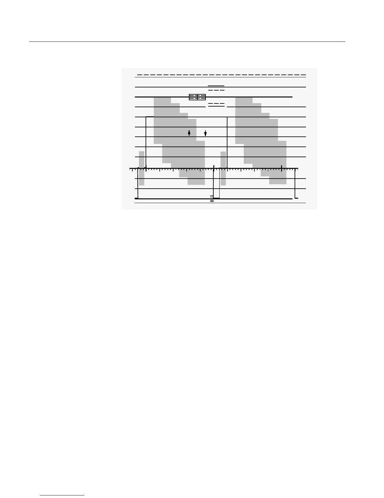
Figure 2-4: Two–line color bar display in FLAT filter mode.
Adjust the SCALE illumination control for the desired graticule scale brightness.
5. Check the Rotation of the Display
Variations in the earth’s magnetic field may make adjustment of the ROTATE
control necessary at installation time or whenever the instrument is moved.
Check that the display blanking level is parallel to the horizontal axis. If not,
adjust the ROTATE screwdriver adjustment until the sweep is parallel to the
horizontal axis.
6. Calibrate Display
The CAL mode on the REF switch enables the waveform monitor calibrator
signal.
Press and hold the REF button until the CAL indicator LED is lit. Adjust the
VERTICAL and HORIZONTAL Position controls to obtain a display similar to
that shown in Figure 2-5.
If necessary, adjust the V CAL screwdriver control for 1 V amplitude (140 IRE).
Switch REF to INT mode.

 Loading...


