1730–Series Installation
3–7
1. Display any standard television waveform. Do not enable the rear-panel
REMOTE connector RGB Enable.
2. Use the 1730-Series HORIZONTAL Position control to align the display
with the graticule.
3. Ground the REMOTE connector RGB Enable (pin 2) and apply the camera
staircase output to the RGB Staircase input (pin 1).
4. Apply the camera video output to the 1730-Series INPUT (CH-A or CH-B)
and select that input with the front-panel INPUT selector.
5. ADJUST — R856 (see Figure 3-1 for location) to center the RGB signal on
the graticule.
6. ADJUST — C953 for the best looking display.
AUXILIARY Connector
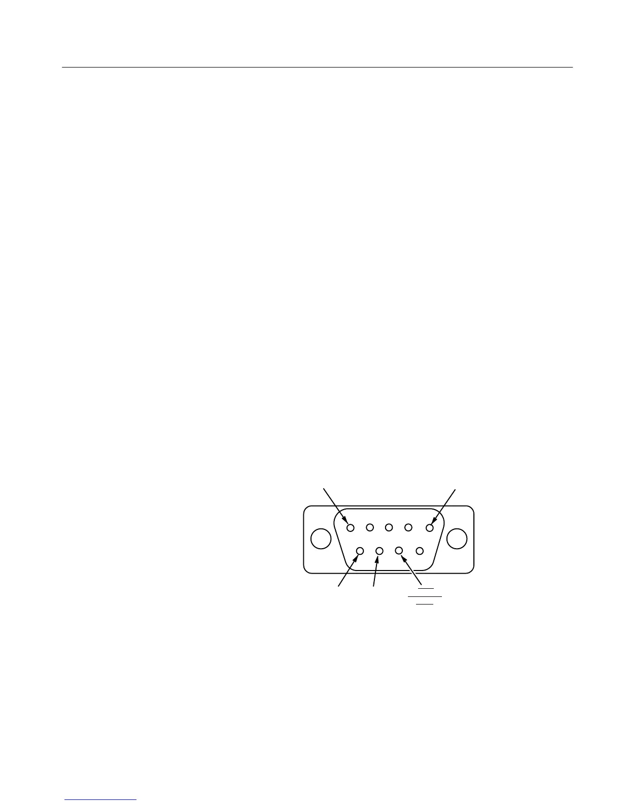
The rear-panel AUXILIARY connector is a 9-pin, D-type connector. It is used to
control the display on a companion 1720-Series Vectorscope. Line and Field
selection information is provided to the Vectorscope over the bus that is
contained in this interface. Figure 3-4 and Table 3–3 show the AUXILIARY
connector pin assignments.
GROUND
GROUND
TXD
RXD
EXT
STROBE
OUT
Figure 3-4: AUXILIARY connector pin functions.
Procedure for setting RGB
Offset

 Loading...


