1730–Series Checks and Adjustments
5–35
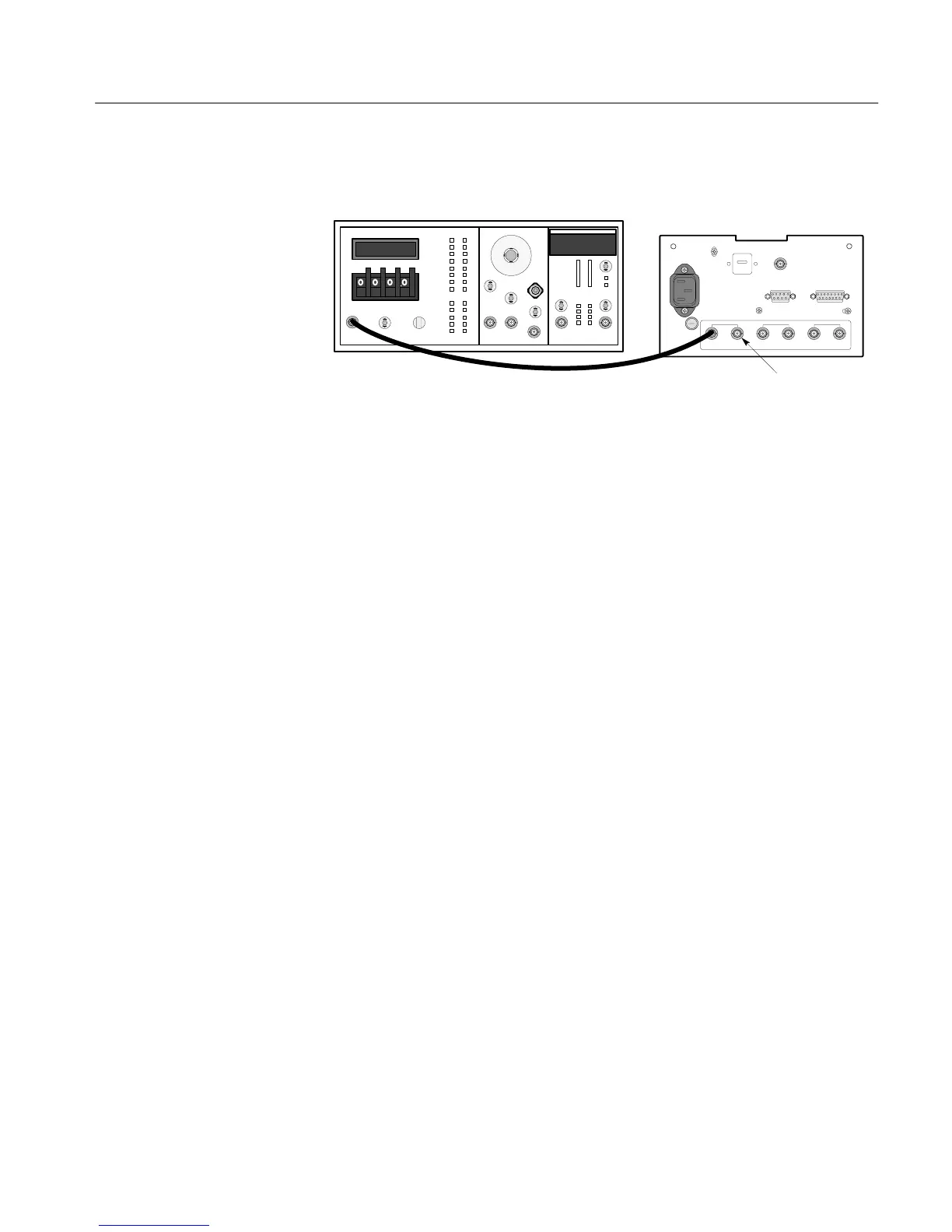
1730-SERIES
(REAR VIEW)
DO NOT
TERMINATE
VAC
Figure 5-10: Equipment setup for adjusting the calibrator amplitude.
b. Set the VAC for 999.9 mV.
c. Adjust the 1730-Series front-panel V CAL so that the VAC signal is
displayed as exactly 1 V p-to-p (140 IRE on the NTSC graticule) on the
CRT graticule.
d. Hold the waveform monitor REF button until the CAL signal replaces
the function generator signal on the display.
e. ADJUST – R689 (Cal Ampl) so that the Calibrator amplitude is 1 V p-p
(140 IRE NTSC) as displayed on the CRT graticule.
14. Adjust Dual Input dc Level
a. Connect the color bar signal through a 75W in-line terminator and a Dual
Input Coupler to the CH–A and CH–B INPUTs. Do not terminate the
loop-through inputs.
b. Connect the black burst signal to the 1730-Series EXT REF and
terminate the loop-through input with a 75W in-line terminator.
c. Set the 1730-Series INPUT to BOTH (CH–A and CH–B).
d. ADJUST – R492 (DC Bal) to overlay the CH–A and CH–B displays.
15. Adjust X5 Magnifier Registration
a. Select CH–A INPUT and GAIN off (no GAIN LED lit).
b. Use the VERTICAL Position control to position the signal blanking
level on the graticule baseline.

 Loading...


