1730–Series Operating Instructions
2–10
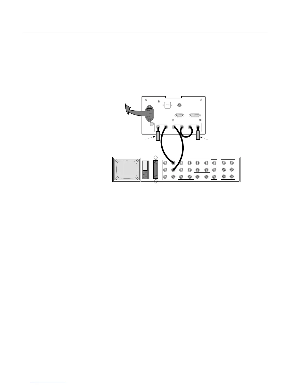
This procedure requires only one hook–up to perform. Figure 2-3 shows the
required connections. Once the connections are made, continue on to step 1 of
the procedure.
1730–SERIES
(REAR VIEW)
1410–SERIES
(REAR VIEW)
POWER
MAINS
COLOR BAR SIGNAL LINEARITY SIGNAL
75W
TERMINATION
75W
TERMINATION
Figure 2-3: Equipment connections for the 1730–Series “Operator’s
Checkout Procedure.”
1. Initial Generator Setup
Video Signal Generator – Test Signals
Full Field Color Bars
75% Ampl. 7.5% Setup – NTSC and PAL–M
75% Ampl. 0% Setup – PAL
Modulated Staircase
(Flat Field, 5 Step)
2. Apply Power
Connect the instrument to a suitable ac power source and push the POWER
button. A center dot should appear in the eye of the POWER switch to indicate
that it is on.
Procedure

 Loading...


