1730–Series Checks and Adjustments
5–36
c. Select X5 GAIN.
d. ADJUST – R274 (X5 Mag) to reposition blanking level to the baseline.
e. Select GAIN off and repeat parts b, c, and d until there is no baseline
shift when switching between off and X5 GAIN.
16. Adjust Channel–A Input Compensation and Flat Response
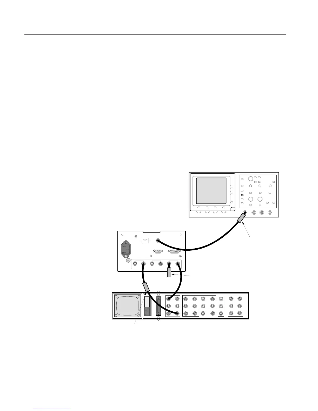
a. Connect the multiburst signal through an in-line 75W termination to the
CH–A INPUT. Connect the black burst signal to the EXT REF and
terminate. Connect a 75W cable from the 1730-Series PIX MON OUT
to the test oscilloscope vertical input (30 MHz vertical plug in). See
Fig. 5-11.
1730-SERIES
(REAR VIEW)
1410-SERIES
(REAR VIEW)
75
TERMINATION
BLACKBURST
75
FEED-THROUGH
TERMINATION
75
FEED-THROUGH
TERMINATION
MULTIBURST
Figure 5-11: Equipment setup for adjusting Channel A input compensation.

 Loading...


