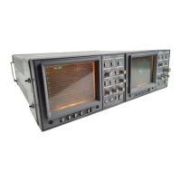
1730–Series Operating Instructions
2–7
standard (after the slight delay associated with automatic determination of the
reference standard).
21 ROTATE
A 270° screwdriver adjustment that aligns the display with the graticule.
22 V CAL
A 270° screwdriver adjustment that sets the vertical amplifier gain. Is normally
used with the CAL position of the REF switch.
23 H CAL
A 270° screwdriver adjustment that sets the timebase. Can be used accurately
with the CAL position of the REF switch in the 2H Sweep.
24 READOUT
A 270° screwdriver adjustment used to change the brightness of the readout
portion of the CRT display relative to the waveform intensity.
Rear–panel Connectors
Signal input, power input, RGB input, Remote Sync Input, Picture Monitor Out,
Auxiliary Control Output, and Remote Control are all located on the 1730–Se-
ries rear panel. Because of the similarity of the 1730– and 1720–Series rear
panels, WAVEFORM MONITOR is printed on the 1730–Series rear panel. See
Figure 2-2 for the locations of the rear–panel connectors.
1 CH–A
Bridging loop–through composite video input, compensated for 75W. This input
is selected for display by the front–panel INPUT switch.
2 CH–B
Bridging loop–through composite video input, compensated for 75W. This input
is selected for display by the front–panel INPUT switch.
Miscellaneous
Bnc Connectors

 Loading...