1730–Series Installation
3–6
A3J540 is moved to the 90 Hz (100 Hz) position (1-2).
A3J635 is moved to the Negative Sync Polarity position (2-3).
In addition to resetting the jumpers, a TTL low (ground closure) on the
REMOTE connector pin 4 is required to enable this trigger mode.
A TTL low level (ground) on pin 2 of the REMOTE connector enables the
shortened RGB/YRGB sweep. A 10-volt square-wave input to pin 1 provides
approximately 9 divisions of sweep. This sweep can be either 1 line or 1 field
depending on front-panel switch setting. The displayed signal is the front-panel
selected CH A or CH B input.
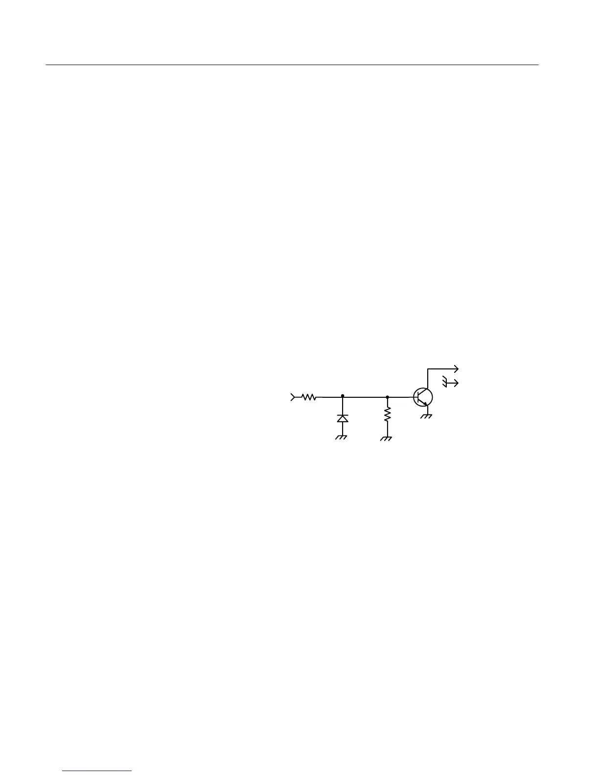
When the 1730-Series Waveform Monitor is substituted for a TEKTRONIX 528
or 528A Waveform Monitor, in some applications the +28 V enable signal used
by the 528 must be converted to ground closure (0 Vdc). This conversion
requires only a few common parts, as shown in Figure 3-3.
1N4152
30V
150 mA
+28V
ENABLING
VOLTAGE
3k
0.25W
47k
0.25W
2N3904
To
1730–Series
REMOTE
connector
Figure 3-3: Common parts used to convert from +28 Vdc enable to ground
closure.
RGB Offset and Compensation — Television cameras vary in output dc level;
R856 is provided to compensate for this variation in dc level. See Figure 3-1.
C953 is the input compensation that matches the Staircase Amplifier input time
constant to the camera output time constant. See Figure 3-1.
Each time the camera input to the 1730-Series is changed the RGB Offset and
input time constant will probably need to be reset. The following procedure
provides a simple means to make these adjustments.
RGB/YRGB Parade
Display

 Loading...


