1730–Series Maintenance
6–22
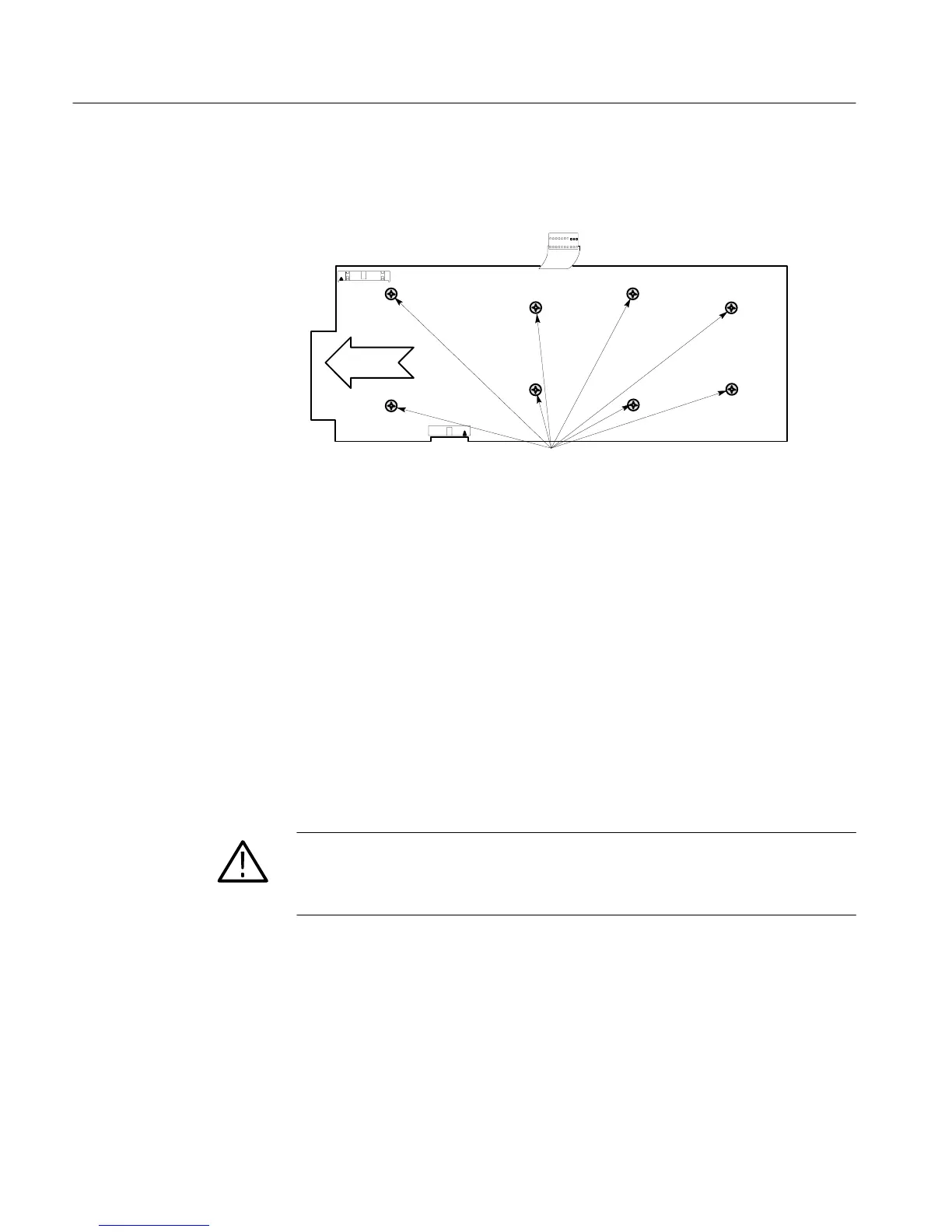
4. Remove the eight screws that are holding the board in place. See
Fig. 6-6 for their locations.
FRONT
J107
J154
Remove these screws to remove this board
J932
Figure 6-6: Screws holding the Main circuit board (A3) in place.
5. Remove the board by sliding it toward the rear panel until the toe of the
board clears the front, then lift out.
6. To replace the Main board, lay the board flat and slide it back into place.
7. To complete the replacement of the board, reverse the rest of the steps.
1. Remove the plug from J4 on the Power Supply board, This is the
connection to the Main board.
2. Remove the anode connection from the CRT and discharge it to ground.
WARNING. CRT Retained Charge Hazard:
3. Unsolder the following connections: J1 pins 1 through 4, J3 pins 1
through 4, and the focus lead at J11. (If a 1700F10 Field Upgrade Kit is
installed, unsolder leads to the rear–panel DC Connector.)
4. Disconnect the ac line filter from the rear panel by unscrewing its two
mounting screws.
5. Use a #1 Pozidrive tip to disconnect the power on/off switch from the
front casting.
Removing the Power
Supply Board
 Loading...


