1730–Series Installation
3–8
Table 3–3: Auxiliary Control Pin Assignments
Pin Function
2-3-4-6 $ $##($#
, &$)#
+(&#! (&$ )( $& # !( !# # $)(%)(
&#'"( ( ,&' ($ ,&'
$"")#($# !#
* ( ,&' ($ ,&'
$"")#($# !#
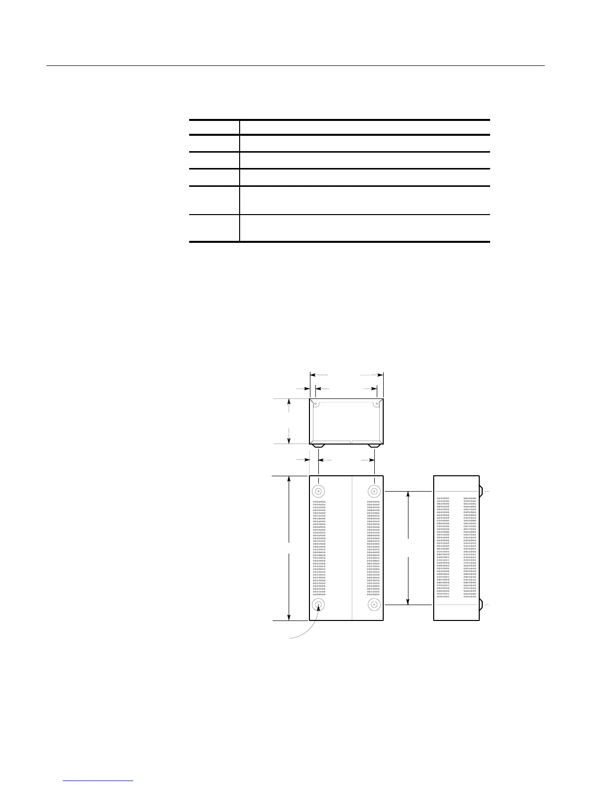
Mechanical Installation
All qualification testing for the 1730-Series was performed in a 1700F00 cabinet.
To guarantee compliance with specifications, the instrument should be operated
in a cabinet. The plain cabinet, 1700F00, is shown in Figure 3-5.
REAR
6.130
BOTTOM SIDE
12.725
8.250
6.8750.688
1.060
16.180
5.105
0.156 DIA.
(4)
Figure 3-5: Dimensions of the 1700F00 plain cabinet.
Cabinets

 Loading...


