1730–Series Installation
3–2
indicated by a box printed on the etched circuit board. Table NO TAG details
these internal jumper selections. Be sure that all operators are aware of changes,
to prevent unnecessary trouble reports, if any of these jumpers are placed in the
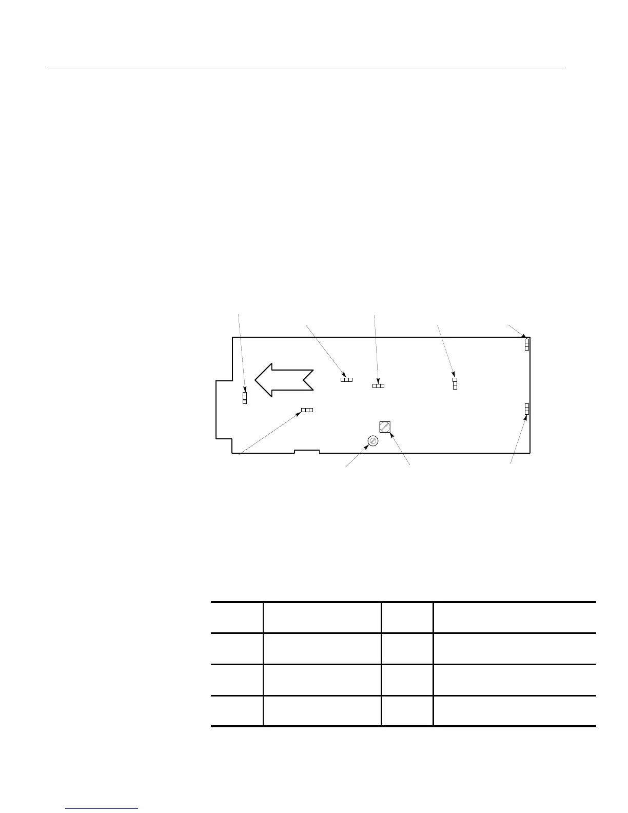
optional position. See Figure 3-1 for location of the internal plug jumpers.
J635
REMOTE
SYNC
POLARITY
J540
90 HZ (100 HZ)
ENABLE
J456
RGB/YRGB
J197
CH A INPUT
COUPLING
J504
50 HZ/60 HZ
J699
CH B INPUT
COUPLING
J99
CLAMP
ENABLE
R856
RGB
OFFSET
C953
RGB
COMP
1
1
1
1
1
1
1
A3 MAIN BD
FRONT
Figure 3-1: Plug jumper locations and RGB compensation adjustments. Pin
1 is denoted by a small numeral 1 next to the plug jumper symbol.
Table 3–1: Internal Jumper Selections
Jumper
Number
Name Position Purpose
&
&
# $"
#! #!% !"#
& $# $ &
&
$ #!% !"#
$
& $# $ &
&
$ #!% !"#
$

 Loading...


